seeliger_00
New member
also have there been updates to the svn site or another version of hydra. svn log shows that the last change was made on october 4th. Seems like a pretty active project to go a month with no changes.
I'm using the DS18B20 sensor, they have them at digi-key. I had some large long syringe needles that had some long caps just large enough to let the sensor slide in. (FYI - aiptasia don't like being injected with kalk and they spread everywhere) :uzi:
You can buy the sensors already waterproofed but they are about $15 more than DIY. I did find these from china: http://cgi.ebay.com/Digital-Thermal-probe-sensor-DS18B20-/350407896599#vi-desc
I finished reading the diy driver thread for the 2nd time yesterday, and have just started reading this thread, and I have a question that would simplify things for me or anyone else that is new to diy electronics. Does anyone know a good website that can explain the basics in layman's terms? I pick up tidbits here and there, but it would be great if I could read an online "tutorial" that explains stuff rather than reading through 30 or so pages making reference to PCB before finally seeing someone say Printed Circuit Board! Things like PWM, pots, shield, header, firmware, I2C, One Wire, etc. I understand the concept and application, but I need to know what the terms mean and what the parts do in order to really grasp it, and I don't want to post "Hey, what is a _______ and what does it do?" everytime I see a new term. I think DWZM stated it perfectly "I want to make this as accessible as possible. People should be able to follow a standard set of instructions using commercially available parts and build this, without having to figure things out on their own.", I just need to be able to understand the discussion. Thanks!
I would be willing to pony up for this order of boards if we can get them for the 30 bucks per DustinB recommendation. I will probably keep 4 of the boards. The others I could send out to some interested parties. Lets wait for DustinB to give the go ahead with the changes.
Fishman and Names will have dibs if I decide to go ahead with the order based on test results from Dustin. Once we are there will organize through PM.
Thanks for the display recommendation Dustin.
Dustin what transisters did you use I should have my SR-8 Tuesday so I will need to be building that as well
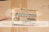
Here's the top of the transistor board, I really need to make the schematic:
And the bottom:


Been sick today so I'll just comment real quick on your schematic. You have A2 & A1 grounded on the mcp23008. They are +5v on mine, that may have something to do with it.
Here's a schematic I was working on yesterday:
Basically I wanted to have one power supply, I made my own wall wart putting out 12v regulated. When it comes into the relay board the LM317 switches it to 7.2v to power the hydra board and the 7805 for the transistors. 12v is also allowed to power the relay strip. I'll try to comment some more on it tomorrow.
")
btw the only reason ours differs on the MCP23008 is because A0,A1,A2 are used to set the addressing, all that affects is the coding.
Another note, seems lke the 7805 gets hot only when the board is connected both to my laptop via FTDI and to the PSU. If I use only the PSU or the FTDI cable everything is cool.
Put a diode in series with the power from the FTDI... if the laptop is less than the voltage from the 7805, then the 7805 is trying to pass current to the laptop via the FTDI.
Is there any easy way to go from schematic to the board without having to redrop all the components?
I wish I could tell you, I'm a little new to eagle myself. I have been unable to edit the schematic without having to do the board over. Maybe DWZM or TeraHz will comment on this. I didn't find much on google.
MA70Snowman, now that I can see straight again for the first time in 2 days, if your board is the same as your schematic, then I "may" see your problem. On the output pins of the port expander you have it going pin->resistor->LED->transistor.
dustin, just a quick side comment as you and me are running similar setups. but wouldn't it be possible, instead of taking a 12V and stepping down, but taking a 5V and stepping UP?
Also, You guys might want to put base load resistors between the MCP23008 output pins and the base of the transistors. I'd check current there when they're on and add a resistor if it looks too high. It's possible that you are exceeding the max current draw of the device and it's shutting off. You don't need THAT much current to turn those transistors on.


