You are using an out of date browser. It may not display this or other websites correctly.
You should upgrade or use an alternative browser.
You should upgrade or use an alternative browser.
My Neptune Apex web interface compatible DIY reef controller
- Thread starter d0ughb0y
- Start date
robsworld78
New member
I plan to switch my connectors from TRRS audio jacks to mini USB conenctors and built this 8 connector board. It holds 8 usb mini type b female (surface mount) connectors

The idea is to be able to pick and choose which sensor or output is needed and assign it to the usb board in whatever order. (the connectors are 4 pin connectors)
Serial2 and Serial3 are for connecting to Atlas stamps. I2C can be used for the atlas stamp as well.
The relay board driver voltage can be 5v or 12v.
Note that those 8 channel relay boards, even if they are 12v boards, the driving signal is still 5v. only the jdvcc is 12v. The actual chauvet relay boards use 12v, so 12v vcc can be selected for this.
The 2 fan output pinout connects directly to a standard 4 pin computer fan.
Hi d0ughb0y, nice work you've done here, looks like you've put a lot into it. I'm also making a complete controller using a Due, Mega 2560 and 7" display. I've been working on it almost a year now and also made up some custom boards. Someone showed me you're new boards mentioning how its similar to mine and I thought I would give you my 2 cents.
My first connector board I used audio jacks like yourself however I found those no good because 2 pins always short out when plugging in or out and sometimes just lose a connection. Then I made a bunch of boards that used the micro USB jack like you're using but honestly they turned out to be more trouble than the audio jacks. Besides being a pain to solder there isn't much holding them to the board so it doesn't take much pressure to lift them. Then I switched to USB-A jacks which turned out be great. Haven't had any problems with them yet. The micros are good but you need a case wrapped around the housing tight so they don't move. Left to right doesn't seem to affect them to much its the up and down motion that's hurts. Either way you a great setup going.
d0ughb0y
Active member
How are you getting on with your led controller board? Looked like just the coding to finish")
software part is a lot harder than the hardware part.
anyway, I setup another teensy to sniff the serial port data between the esp wifi and the main teensy, and I can see esp is sending the complete data, so I don't think there is an issue with esp as I first thought. I was using readbytesUntil and find function which is what's causing those extra connect and ipd messages from esp to be lost. I have to revise my esp library.
I desoldered the 12v buck converter from my led board. it was not hard at all since it used a large pad hole. I am still waiting for the replacement 12v buck converter. I watched a youtube video that shows an HV buck converter that shuts down and runs hot when higher than 30V is applied, which looks like exactly what happened to my buck converter. The video showed the red colored boards seem to be able to handle the higher input voltage, so I got the red colored buck converter board for replacement. I'll see if that works better.
Hi d0ughb0y, nice work you've done here, looks like you've put a lot into it. I'm also making a complete controller using a Due, Mega 2560 and 7" display. I've been working on it almost a year now and also made up some custom boards. Someone showed me you're new boards mentioning how its similar to mine and I thought I would give you my 2 cents.
My first connector board I used audio jacks like yourself however I found those no good because 2 pins always short out when plugging in or out and sometimes just lose a connection. Then I made a bunch of boards that used the micro USB jack like you're using but honestly they turned out to be more trouble than the audio jacks. Besides being a pain to solder there isn't much holding them to the board so it doesn't take much pressure to lift them. Then I switched to USB-A jacks which turned out be great. Haven't had any problems with them yet. The micros are good but you need a case wrapped around the housing tight so they don't move. Left to right doesn't seem to affect them to much its the up and down motion that's hurts. Either way you a great setup going.
regarding audio jack, if you connect power line to the "tip" and the gnd to the "sleeve", then it is physically impossible to short the power to the ground. I was initially having this issue as well until I figured the proper way to connect.
I realize the usb mini can be hard to solder, so I'll probably get a stencil for it to get the solder paste exactly to the usb mini pins pads.
I have very limited space inside the chauvet, and connectors can only be 1/2 inch apart, so my only other choice is usb mini. Audio connectors (the jack and plug) are either hard to find or are ridiculously expensive, particularly the TRRS, that's why I am switching to usb connector.
I still want to keep the cost of this project to be around $100 (plus the cost of atlas stamps and probes) so anyone can do it without spending $500 or more on a controller.
robsworld78
New member
But there are 3 connections to make, ground, power and data, so something has to short out. Why did you change? If you have a hot air soldering station then soldering them is pretty easy you just need to play nice with them. You shouldn't need a stencil as the solder paste finds its way to the pins no problem. I just got a hot air station and I'm loving the thing.regarding audio jack, if you connect power line to the "tip" and the gnd to the "sleeve", then it is physically impossible to short the power to the ground. I was initially having this issue as well until I figured the proper way to connect.
I realize the usb mini can be hard to solder, so I'll probably get a stencil for it to get the solder paste exactly to the usb mini pins pads.
I have very limited space inside the chauvet, and connectors can only be 1/2 inch apart, so my only other choice is usb mini. Audio connectors (the jack and plug) are either hard to find or are ridiculously expensive, particularly the TRRS, that's why I am switching to usb connector.
I still want to keep the cost of this project to be around $100 (plus the cost of atlas stamps and probes) so anyone can do it without spending $500 or more on a controller.
Last edited:
Moomin1967
New member
Hi,
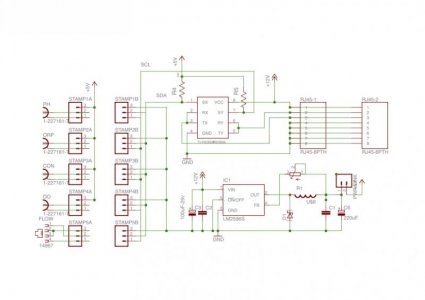
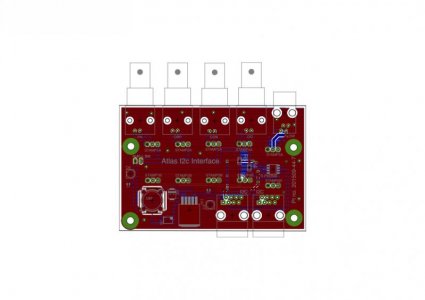
Im persisting with a modular appraoch to the controller, I have put this board together which is an Atlas I2C interface board.
I have used a TI- P82B96 as an I2C bidirectional bus driver, which should allow for a connection of upto 20m. I intend to also integrate into my greenhouse control system. (Hence the modular approach).
A bus master would need to be added to the chauvet controller for this to work, its essentially the same P82B96 configuration with a couple of bus pull ups
I have yet to prototype it, so if there is anythng obvious plese do let e know.
Thanks for the ongoing commitment and inspiration D0ughb0Y.
M
Attachments
d0ughb0y
Active member
But there are 3 connections to make, ground, power and data, so something has to short out. Why did you change? If you have a hot air soldering station then soldering them is pretty easy you just need to play nice with them. You shouldn't need a stencil as the solder paste finds its way to the pins no problem. I just got a hot air station and I'm loving the thing.
for parts with smd pads under the component, like the pins of the usb mini connector, if you over apply the solder paste, it will cause a bridge that you will not be able to fix. Due to small pads, excess solder will have nowhere to go except to bridge. I suppose if you can manually apply very little solder paste, then it should not be a problem. I found oshstencils can make stencils for $5, so I figure that may be the way to go.
it will "short", but there is no consequence.
Lets take OneWire temp connection as an example
You have +5v, data and Gnd. data has pullup connection to +5v.
if you insert the plug, tip contacts gnd - no issue.
push it in to next stage, tip contacts data, data contacts gnd.
the plug tip will be receiving some power, through the pullup resistor to +5, but since gnd is not connected, and data is connected to gnd, there is no issue.
push it in one more, tip contacts +5v, data contacts data, gnd contacts gnd and completes the circuit.
with usb, you don't need to worry about these connection ordering.
I did want to make sure I connect gnd and +v to the proper USB +v and gnd pins. The only change I made is to not connect the gnd pin on the doser pump port, as +v is 12v and will damage a 5v device.
I changed because I find the price of TRRS connectors to be insanely expensive. Even building the custom usb pcb, the total cost for 8 ports is less than half if I were to use audio jack. I wanted to make all connectors 4 pins so I can easily switch placement/order by simply switching the pin header connections around.
robsworld78
New member
Good to know about the soldering, I'm new to hot air. I apply manually so maybe that's why I haven't had any problems, its not fun dabbing the solder paste, I didn't realize stencils were so cheap, I'm definitely getting some.
I found the same thing with audio jacks, I couldn't believe how much they cost. These USB's are very cheap, all types, and feel so much better than those did, I used cheap ones. I think the USB can handle more current to, the big ones are good for 2amps I think micro was 1.5 or something which is plenty.
One of these days I'll have to go through backwards to see whats going on, bad thing about showing up late. Anyways good luck with everything.
Hello d0ughb0y, thank you for your great system. I put it in the balcony of my house of the fish dishes symbiotic system. Very good! But 10 days ago the typhoon broke my Internet. 3 days later I found no Internet, I can not log in the LAN Chauvet16. How to modify what is not the need to be able to land in the local area network can also be Chauvet16?
d0ughb0y
Active member
yes I know it is a problem if there is no internet.
The main html page has links to javascript that needs to be downloaded from the internet, so even if you have your local network up, it won't be able to load the javascript files. You can download and place those files in the SD card (change the filename to short filenames), then edit the main html to reference those instead.
On the new version of the controller, my plan is to make the esp wifi module run in AP mode, so even if there is no router, you will be able to connect to the controller from your smartphone.
d0ughb0y
Active member
I got the esp8266 wifi to work since a week or two ago, but I found out realistically, 115200 baud is too slow. At best it can send 10k in 1 second so I started testing at higher baud rate. esp8266 supports baud up to 4608000 baud max. That's 4.6 megabits/sec, which is pretty decent, if it works. The problem is, it does not work. espressif is telling me I need hardware handshake for it to work. But ESP-01 does not have the RTS/CTS pins available. Upon further testing, I see the problem only occurs if I send data 2k at a time, but not if I send at 1k at a time even at 4.6mbaud. If that speed is acceptable, then that is what I'll use. Otherwise, I might have to change the design to use a different esp module. I will test RTS/CTS using the olimex module I bought a while back.
d0ughb0y
Active member
I tested the esp8266 connection with hardware handshake, and the data transfers are all 100% complete. I am sending at max allowable baud and data to esp8266, which is 4608000 baud and 2048 bytes.
I will be modifying the led controller circuit to use hardware handshake.
I'm deciding whether to use ESP-03 or ESP-12. I think the ESP-12 is more popular since all the pins of the chip are available. It is slightly larger in size than ESP-01.
I have a few other minor improvements I need to make anyway. I am thinking of adding power monitoring to the controller. I think it will be useful information to know how much power the LED fixture is consuming.
BTW, PJRC decided all of a sudden to discontinue teensy 3.1 and replace it with teensy 3.2, for which the through hole pins are the same as 3.1. If you already have a 3.1, that will still work on pcb I am going to make.
robsworld78
New member
I'll be interested to see how you do the power monitoring, that's something I would love to add but so much of this is over my head. Does it take much hardware? You said you wanted to keep the cost down so I'm assuming not?
d0ughb0y
Active member
I'm still researching. I just got two ACS712 modules, they are less than $2 each. I have not wired it up to test it yet. It measures current. So for the LED, I know the input voltage is 48V so I can calculate the power consumption from there. For the chauvet controller, I'm going to hook it up to the AC mains to monitor total power consumption. I got a 5A version for the LED controller and a 20A version for the chauvet controller. The 20A can only measure max 14 amps RMS AC, I I think that range should work for most if not all users.
d0ughb0y
Active member
Just an update.
I just finished coding update to Serial library to make it truly support hardware handshake.
https://forum.pjrc.com/threads/2944...-Control-RTS-CTS?p=83062&viewfull=1#post83062
Arduino library, including teensy never really supported hardware handshake. I think AVR processors do not support them, I think that's the reason original arduino library never had them. But ARM processors support them but teensy library does not have code to use the feature.
Anyway, I got a solid base code so I can continue working on the rest of the code. I still have to update the circuit to use rts/cts and other changes and order pcbs again.
With hardware handshake, I can transfer data between teensy and esp8266 at 4.6mega bit/sec. That's still slow considering wifi can go 30-50 or over megabit/sec. But it is going to be at a decent speed. I was comparing the data transfer time of esp8266 at 4.6megabit/sec vs wired ethernet using mega with ethernet shield, and it is still slower, but I think it is now acceptable.
I am thinking of implementing websocket protocol rfc6455 (not sure if there are libraries available). The current chauvet controller uses ajax/json rest service calls in javascript to retrieve data maybe updates once or twice per second (the pwm pumps bar graph display). With websocket, which pretty much all browsers support, it will be truly real time data transfer. And for this to work, I need the serial transfer to be 100% reliable, that's why I need to make the rts/cts work first.
also, the esp8266 is perfect because it can operate in both infrastructure mode (where it connects to your router) or AP mode (where it has its own wifi network that you can connect to), and both can run at the same time. This will solve the problem of no access to the controller in case router is down. Most modern electronics that has wifi support both modes.
Last edited:
d0ughb0y
Active member
I wish I had more time to work on this. A lot of patience is required.
I got an esp-12e really fast. I ordered it on ebay on friday and shipped from china same day and got it on tuesday. It's almost as fast as domestic shipping at a fraction of the cost.
I tested it and it works fine. It comes with 32mbit flash, though I don't need all that for this application. 4mbit flash works just fine. The size of the board is about the same as esp-01, but it is a surface mount board, but not hard to solder.
I also got a few esp-03 but have not tested yet. these are a lot smaller than the esp-12 and comes with ceramic antenna. If this gets stronger wifi signal, then I will go with the 03, otherwise, I think I will be using the esp-12.
I am working next on the code to enable both AP and infrastructure mode on the esp8266 so it can be accessed directly from a smartphone, or via router.
I have not tested the ACS712 current sensor yet, and will probably do that this weekend. And update and reorder the pcb.
d0ughb0y
Active member
I'm working on updating the circuit for the led controller, and was looking up parts and noticed there are led driver chips that costs less than half of meanwell ldd drivers. They do need additional external components like a resistor, capacitor and inductor, but the footprint is way smaller than the meanwell ldd and dimmable via pwm. I was wondering if anyone else have tried these. They come mostly as 1amp constant current driver. Those multichip leds usually require 700ma, or 1a and some 1.5amp with lower voltage. The chip also has 5v output that can be used to power other circuits. I think this will reduce the board size quite a bit and component count as well and also cost.
just did a quick search on ebay, and it is essentially this
http://www.ebay.com/itm/1X-5-35V-3W...ant-Current-/301543101620?hash=item46355e94b4
I suppose with the additional parts (diode, inductor, resistor and capacitor), the amount of space taken would not be too different from meanwell ldd.
BTW, ESP-03 is not usable, there is no connection to reset pin!!. I think I'll use esp-12. It is the latest and seems to be stable and can be socketed using 1.27mm pitch header and socket.
Last edited:
I had a hard drive failer and had to reload windows, i did manage to save my sketch files but now i cant get it to compile correctly any thoughts?
thank you
Code:
Network.ino: In function 'void logNetworkAccess(TinyWebServer&)':
Network:541: error: 'class EthernetClient' has no member named 'getRemoteIP'
Utils.ino: In function 'void getfiles(EthernetClient&, char*)':
Utils:637: error: 'class SdFile' has no member named 'getFilename'd0ughb0y
Active member
you need to edit the Ethernet library. The instructions are in the github page.
update.
I was almost ready to submit rev2 of the LED controller pcb then I thought I might as well add pins for pushbuttons. So I added 2 pins for touch sense buttons. The 2 lines will work as 3 buttons. So I am finishing the pcb update so I can submit it in a couple days.
update.
I was almost ready to submit rev2 of the LED controller pcb then I thought I might as well add pins for pushbuttons. So I added 2 pins for touch sense buttons. The 2 lines will work as 3 buttons. So I am finishing the pcb update so I can submit it in a couple days.
you need to edit the Ethernet library. The instructions are in the github page.
update.
I was almost ready to submit rev2 of the LED controller pcb then I thought I might as well add pins for pushbuttons. So I added 2 pins for touch sense buttons. The 2 lines will work as 3 buttons. So I am finishing the pcb update so I can submit it in a couple days.
ok i thought i had done that already but maybe not. i will give it a try thank you
edit, still having the same error for the last 2 lines that i posed befor. any thoughts?
Last edited:
Similar threads
- Replies
- 0
- Views
- 1K
- Replies
- 1
- Views
- 683
- Replies
- 0
- Views
- 994