I am not sure if your question is in reference to my build or Durso standpipes in general so I will try to explain from both perspectives in somewhat layman terms. This is all covered on my site and the first page of this thread, but it may be worth repeating.
When water falls through a pipe it can behave in several different ways. If the water volume is not sufficient to fill the pipe and the flow is somewhat smooth (laminar) then the water will cling to the pipe walls. This allows air to be present in the pipe with overall little effect on the way the water flows. As the flow increases (with relation to the area of the pipe) the water will begin to tumble and churn as it drops. In doing so, the water begins to create suction (a pressure drop) above it. If no air is allowed into the pipe, then the flow will begin to form a siphon. That is the "suction" will pull water from the intake pool. The rate of flow is a pure function of the pipe diameter (at is smallest point) and the net drop (head) between the intake pool and discharge pool heights connected to the pipe.
If the pipe has an opening at the top, that same suction that is trying to draw water in, will also draw air in. The air that is drawn in displaces water and therefore decreases the overall flow through the standpipe. As the air mixes with the water it also creates turbulance and the tubulnace also reduces the flow in the standpipe.
A "Durso" functions (or is tuned) by adjusting the amount of air that is allowed to enter the standpipe. Adjusting the amount of air adjusts the amount of water and the amount of turbulance. The idea is to get the "two phase" flow to be stable and quiet. The reality is that for a given standpipe size and height, the range of "quiet and stable" flow that that can be tuned to the standpipe is very small. A side effect is that the the air sucked into the standpipe gets chruned into tiny bubbles and ejected at the discharge.
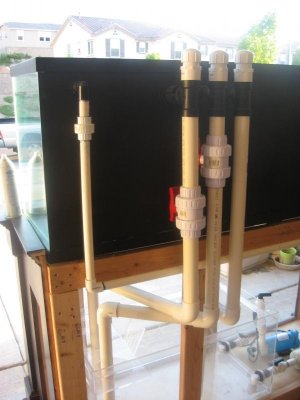
In my design, the standpipe IS NOT regulated by air. The air volume allowed to enter the standpipe must be sufficient to allow the single phase laminar (water clinging to the pipe walls) flow. The VALVE is NOT needed and there ARE NO ADJUSTMENTS. The Valve only serves as a maintenance tool if needed. The TUBE is part of the fail-safe system. It is connected to the standpipe and curled over and attached just above the normal operating level of the overflow box. If, for any reason, the water rises to this level, the air intake will become blocked with water and seal the standpipe, turning it into a full siphon.
My design does not function as a "Durso" or "Stockman". The references to those designs are from a mechanical standpoint, not a functional standpoint. That is, the purpose of mentioning them was to convey how they are constructed and further to outline how they differ in function.
This fail-safe feature can be used on just about ANY Durso or Stockman standpipe.
Hope that makes sense.
")