Who wants a cheap, simple, Arduino-based LED controller?

OK, So in the earlier thread you had said that you have to be careful if the frequencies were too close. I didn't quite understand that. So am I to understand that my diagram should work? It the negatives will be going to a breadboard where I have 2 2N2222A transistors and 2 1k resistors. ONe for each color. They will then wire to two arduino PWM pins. Does this sound right?
 
Frequencies only really matter if you were trying to "mix" the arduino-based controller with that other PWM controller. If you are ONLY going to use the arduino-based controller (either your own design or the Typhon) it is no longer an issue.

Your description of that breadboard circuit is more or less correct, an Arduino output pin connects to a resistor that connects to the base pin on the npn transistor. The collector of the transistor connects to the "-" wire from the driver's dimming circuit, and the emitter of the transistor connects to ground. Then you need a 10v supply, with the positive connected to the "+" wire from the driver's dimming circuit, and the ground tied to the Arduino's ground. The lucky thing with using a Typhon is that this is all built right in to the mainboard so all you need to do is give it power and wire it to the drivers.
 
Some of us are total nobs when it comes to electronics. I have at least made a couple of LED fixtures.

Anyway it has been asked previously in this thread about a housing to cover the Typhoon with a view window and buttons. From a Nob's perspective I do not know that the question has been adequately answered.

DWZM did reply about using a plastic electrical box and I understand that, but on the button issue I'm still in the dark.

I"m not real good at looking up electronic components on Digikey because I don't understand exactly what I need from a voltage/amperage perspective to substitute for the exisiting buttons or where to look for button extensions which DWZM used.

I know that I'm not the only one on RC that would benefit from this request. Could someone be kind enough to supply a link to buttons that could be used for this, plus a basic level instruction on how to hook them up? I for one would deeply appreciate this. Thanks!
 
Great thread guys. Haven't had time to read the whole thing yet but I got a quick question.

A friend of mine got a typhon from another hobbiest. The previous owner had uploaded a sketch to reverse the modulated signal on the controller. I don't think he used it very long before purchasing a new one and sending his old one to my friend. My friend is telling me that the timer keeps freezing up. It runs, then stops, then runs again...etc. After about an hour the timer ends up several minutes behind.

Could this be an issue from the new sketch or is the timer going bad?
 
Hey all,

Am starting on an Open Source Android App for use with the Typhon and was wondering if anyone is really good at using Eclipse and willing to help me on this....on completion it'll be free on the app market for those of us using the Typhon and would like to use their Android with it....just a thought.
 
Adapting Typhon code

Adapting Typhon code

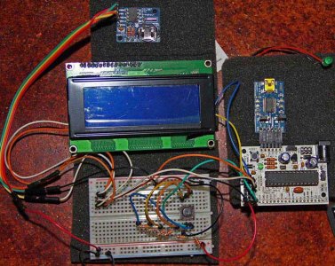
Over the last few months I've been building an Arduino controller for my tank. I would like to have these features when its all done: 2 LED main channels, 1 moonlight channel, Temp, pH, Heater, ATS and the last phase would add the Arduino ethernet shield.

I tried to adapted the original Typhon code and tried using Spuzzum's ADC code. I can't figure out how to alter the typhon code to work with my hardware. Using the i2c saves me pins but completely changes the way clicks are monitored. The problem is passing the key movement to the old code. I've tried to adapt the code but its way above my programming skills.

Here is what I have...

Hardware
Modern Device's Bare-bones Freeduino
Adafruit DS1307 RTC using i2c
Modern Device's USB BUB II
Adafruit 20x4 Standard HD44780 LCD
Adafruit i2c LCD backpack
5 way joystick switch that uses 5 resistors (a.k.a. ADC joystick)

Joel's Controller current PinOuts
* ------------------------------
* 0 {Heater} .................. A0 Keypad (5 switch Joystick)
* 1 {ATS} ..................... A1
* 2 ............................... A2
* 3 {MOON LED} PWM ..... A3
* 4 Ethernet/SDcard ....... A4 i2c DAT (LCD&RTC)
* 5 LED 1 PWM .............. A5 i2c CLK (LCD&RTC)
* 6 LED 2 PWM
* 7
* 8 {TEMP}
* 9 {LED} PWM [BACKLTH not used with current LCD]
* 10 Ethernet/SDcard
* 11 Ethernet/SDcard
* 12 Ethernet/SDcard
* 13 Ethernet/SDcard
* -------------------------------
Items in {These} brackets indicates possible location for feature
 

Attachments

  • Arduino-controller.jpg
    Arduino-controller.jpg
    100.6 KB · Views: 5
Last edited:
Hey all,

Am starting on an Open Source Android App for use with the Typhon and was wondering if anyone is really good at using Eclipse and willing to help me on this....on completion it'll be free on the app market for those of us using the Typhon and would like to use their Android with it....just a thought.

That's an interesting concept. I know a few other people doing reef controller work with Arduinos who have linked them to Andriod phones. It might make sense to make your effort generic instead of specifically attached to the Typhon project, since it'll require pretty significant coding on the AVR that isn't part of the Typhon core project.

You mentioned putting it on the App store for free, which is generous. As a friendly reminder, since moving in this direction might bring some new visibility to the Typhon controller, the hardware is currently licensed under CC 3.0 by-sa-nc, which means it can't be sold commercially, you are free to use it for personal use, and any work done with the Typhon as it's core MUST be attributed to this project and released under the same license (i.e. you can't base something on the current Typhon hardware and then sell it).

joelatx,

Have you gotten the individual components working on their own? i.e. plug ONE bit of hardware into the freeduino, and load a sketch that ONLY tests that piece? That's always my starting point when adapting hardware and mixing different sources for sub-components.
 
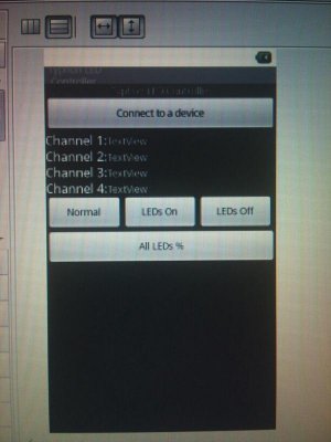
I've been playing with it for the past few days and finally have the BT module pairing to the cell. I just need to work on getting the buttons to send the serial info for the buttons and add a % slider to it. I've managed to get the test serial coding to work using a BT terminal for the cell to work to turn lights to Timer,All Max and All Min.....not sure how to do the % part yet. But here is a pic of the beginnings of the app. I still need to add another page for the about section to include the contributor names and a button for a link to this thread.
 

Attachments

  • mms_img29695.jpg
    mms_img29695.jpg
    58.7 KB · Views: 5
Yes all the individual parts are working, (excluding the ethernet, that's later) I have been able to get Spuzzum's ADC test code to work, and I'm able to add the clock to that code and it displays. I can load the typhon code, and it displays the normal menu (but of course the buttons don't work.)

The Typhon code uses a "CheckButtonAction" or some other method to catch the key presses on individual pins. The ADC keyboard uses the i2c bus and I'm having trouble sending (catching) something the old code can understand. I can post code samples once I get home, if that will help.
 
Last edited:
Quick question. Is the Typhon board more or less to control LED's or has it been updated or modified to do a bit more such as report water temp? Or should I be looking at the other project in the DIY section?

I have two bio-cubes which support dimmable LED's (one using Steve's and the other using Rapid's) but wanted to report temp as well. Controlling pumps to feed would be grand as would a data logger but honestly I have to keep costs down :) Sorry if this has been asked before.

Oh - are the build of material lists out there on google still current or up to date?
 
saltydogaqua,
What kind of shield are you going to use for communication? :reading:
shark boy


Hey all,

Am starting on an Open Source Android App for use with the Typhon and was wondering if anyone is really good at using Eclipse and willing to help me on this....on completion it'll be free on the app market for those of us using the Typhon and would like to use their Android with it....just a thought.
 
The BOM on google is more or less up to date. I just used it to order parts last week and everything from Mouser was in stock.

The Typhon was really designed to control LEDs, with the potential for expansion. There's nothing in the core project to do what you're describing out of the box, but the potential is definitely there. A popular way to get temps is to use one wire temp sensors (DS1820). A popular way to read switch states and turn pumps on and off would be to use an I2C I/O berakout board (see the one that's a part of the Hydra project) with a relay board.

Speaking of the Hydra, it was really designed from the ground up to be a whole-tank controller, so it has some things out of the box that the Typhon does not have. But, of course, they're both Arduino-based, so they basically have the same potential functionality. It's really a matter of what comes out of the box as part of the design vs. what you have to build yourself.
 
Code I've been using

Code I've been using

OK here is the code with working buttons with a clock on the display.

Code:
/*
 * Spuzzum's ADC buttons
 * TimeRTC.pde
 * example code illustrating Time library with Real Time Clock.
 * 
 */

//#include "Time.h"  
#include "Wire.h"  
#include "RTClib.h" // #include <DS1307RTC.h>  // a basic DS1307 library that returns time as a time_t
#include "LiquidCrystal.h"

RTC_DS1307 RTC;


LiquidCrystal lcd(0);

// define some values used by the panel and buttons
int lcd_key     = 0;
int adc_key_in  = 0;
#define btnRIGHT  0
#define btnUP     1
#define btnDOWN   2
#define btnLEFT   3
#define btnSELECT 4
#define btnNONE   5

// read the buttons
int read_LCD_buttons()
{
  adc_key_in = analogRead(0);      // read the value from the sensor 
  // my buttons when read are centered at these valies: 0, 144, 329, 504, 741
  // we add approx 50 to those values and check to see if we are close
  if (adc_key_in > 1000) return btnNONE; // We make this the 1st option for speed reasons since it will be the most likely result
  if (adc_key_in < 50)   return btnRIGHT;  
  if (adc_key_in < 200)  return btnUP; 
  if (adc_key_in < 400)  return btnDOWN; 
  if (adc_key_in < 600)  return btnLEFT; 
  if (adc_key_in < 800)  return btnSELECT;   
  return btnNONE;  // when all others fail, return this...
}

void setup()  {
  Serial.begin(57600);
  Wire.begin();
  RTC.begin();
  RTC.adjust(DateTime(__DATE__, __TIME__));
  /* if (! RTC.isrunning()) {
   Serial.println("RTC is NOT running!");
   // following line sets the RTC to the date & time this sketch was compiled
   RTC.adjust(DateTime(__DATE__, __TIME__));
   }
   */

  // set up the LCD's number of rows and columns: 
  lcd.begin(20, 4);
  lcd.clear(); // Clear Display
  lcd.setBacklight(HIGH);
  lcd.setCursor(5,0); // Place cursor row 6, 1st line (counting from 0)
  lcd.print("Setup");
  lcd.setCursor(7,1); // Place cursor row 8, 2nd line (counting from 0)
  lcd.print("ok");
  delay(2000);
  lcd.clear();
  lcd.setCursor(2,0);
  lcd.print("ADC Key Test");  
  delay(100);
  lcd.clear();
}

void loop()
{

  digitalClockDisplay();  
  delay(1000);
  //lcd.clear(); // Clear Display


lcd.setCursor(4,0);
  lcd.print("ADC Key Test");  

  {
    //lcd.setCursor(9,1);            // move cursor to second line "1" and 9 spaces over
    //lcd.print(millis()/1000);      // display seconds elapsed since power-up


    lcd.setCursor(0,1);            // move to the begining of the second line
    lcd_key = read_LCD_buttons();  // read the buttons

      switch (lcd_key)               // depending on which button was pushed, we perform an action
    {
    case btnRIGHT:
      {
        lcd.setCursor(5,2);
        lcd.print("RIGHT ");
        delay(1000);
        break;
      }
    case btnLEFT:
      { 
        lcd.setCursor(5,2);
        lcd.print("LEFT ");
        delay(1000);
        break;
      }
    case btnUP:
      { 
        lcd.setCursor(5,2);
        lcd.print("UP    ");
        delay(1000);     
        break;
      }
    case btnDOWN:
      {  
        lcd.setCursor(5,2);
        lcd.print("DOWN  ");
        delay(1000);
        break;
      }
    case btnSELECT:
      {
        lcd.setCursor(5,2);
        lcd.print("SELECT");
        delay(1000);
        break;
      }
    case btnNONE:
      { 
        lcd.setCursor(5,2);  
        lcd.print("NONE  ");
        break;
      }

    }

  }

}

void digitalClockDisplay(){

  DateTime now = RTC.now(); 
  // digital clock display of the time
  lcd.setCursor(0,3);
//lcd.setCursor(2,0);
    
  lcd.print(now.month());
  lcd.print("/");
  lcd.print(now.day());
  lcd.print("/");
  lcd.print(now.year());
  lcd.print(" ");
  lcd.print(now.hour());
  printDigits(now.minute());
  printDigits(now.second());


  //lcd.println(); 
}

void printDigits(int digits){
  // utility function for digital clock display: prints preceding colon and leading 0
  lcd.print(":");
  if(digits < 10)
    lcd.print('0');
  lcd.print(digits);
}
 
This one also works, it uses fewer lines of code for the buttons. Don't know if it would be easier to adapt.

Code:
/*
 * Building Control
 * ADC and Clock - version 3
 * Can't remember where this came from
 */
#include "Wire.h"  
#include "RTClib.h" // #include <DS1307RTC.h>  // a basic DS1307 library that returns time as a time_t
#include "LiquidCrystal.h"

RTC_DS1307 RTC;

LiquidCrystal lcd(0);

// define some values used by the panel and buttons
#define btnRIGHT  0
#define btnUP     1
#define btnDOWN   2
#define btnLEFT   3
#define btnSELECT 4
#define btnNONE   5


//ADKeyboard Module
int adc_key_val[6] ={
  50, 200, 400, 600, 800, 1600 };
int NUM_KEYS = 6;
int adc_key_in;
int key=-1;
int oldkey=-1;


void setup()
{
  pinMode(13, OUTPUT);  //we'll use the debug LED to output a heartbeat
  Serial.begin(57600); // 57600 bps
  Wire.begin();
  RTC.begin();
  RTC.adjust(DateTime(__DATE__, __TIME__));
  /* if (! RTC.isrunning()) {
   Serial.println("RTC is NOT running!");
   // following line sets the RTC to the date & time this sketch was compiled
   RTC.adjust(DateTime(__DATE__, __TIME__));
   }
   */

  // set up the LCD's number of rows and columns: 
  lcd.begin(20, 4);
  lcd.clear(); // Clear Display
  lcd.setBacklight(HIGH);
  lcd.setCursor(5,0); // Place cursor row 6, 1st line (counting from 0)
  lcd.print("Setup");
  lcd.setCursor(7,1); // Place cursor row 8, 2nd line (counting from 0)
  lcd.print("ok");
  delay(2000);
  lcd.clear();
  lcd.setCursor(2,0);
  lcd.print("ADC Key Test");  
  delay(100);
  lcd.clear();

}
void loop()
{
  digitalClockDisplay();

  adc_key_in = analogRead(0);    // read the value from the sensor 
  digitalWrite(13,LOW); 
  key = get_key(adc_key_in);  // convert into key press

  if (key != oldkey)   // if keypress is detected
  {
    delay(50);  // wait for debounce time
    adc_key_in = analogRead(0);    // read the value from the sensor 
    key = get_key(adc_key_in);    // convert into key press
    if (key != oldkey)    
    {   
      oldkey = key;
      if (key >=0){
        digitalWrite(13,HIGH);
        switch(key)
        {
        case 0:
          Serial.println("Right OK");
          lcd.setCursor(2,1);
          lcd.print("Right OK  ");
          break;
        case 1:
          Serial.println("Up OK     ");   
          lcd.setCursor(2,1);
          lcd.print("Up OK     ");
          break;
        case 2:
          Serial.println("Down OK   ");   
          lcd.setCursor(2,1);
          lcd.print("Down OK ");
          break;
        case 3:
          Serial.println("Left OK    ");   
          lcd.setCursor(2,1);
          lcd.print("Left OK  ");
          break;      
        case 4:
          Serial.println("Select OK");   
          lcd.setCursor(2,1);
          lcd.print("Select OK   ");
          break;
        case 5:
          Serial.println("Push Button");   
          lcd.setCursor(2,1);
          lcd.print("Push Button");
          break;   
        }                
      }
    }
  }
  delay(100);
}
// Convert ADC value to key number
int get_key(unsigned int input)
{
  int k;
  for (k = 0; k < NUM_KEYS; k++)
  {
    if (input < adc_key_val[k])
    {
      return k;
    }
  }
  if (k >= NUM_KEYS)k = -1;  // No valid key pressed
  return k;
}

void digitalClockDisplay(){

  DateTime now = RTC.now(); 
  // digital clock display of the time
  lcd.setCursor(0,3);
  //lcd.setCursor(2,0);

  lcd.print(now.month());
  lcd.print("/");
  lcd.print(now.day());
  lcd.print("/");
  lcd.print(now.year());
  lcd.print("   ");
  lcd.print(now.hour());
  printDigits(now.minute());
  printDigits(now.second());


  //lcd.println(); 
}

void printDigits(int digits){
  // utility function for digital clock display: prints preceding colon and leading 0
  lcd.print(":");
  if(digits < 10)
    lcd.print('0');
  lcd.print(digits);
}
 
saltydogaqua said:
Hey all,

Am starting on an Open Source Android App for use with the Typhon and was wondering if anyone is really good at using Eclipse and willing to help me on this....on completion it'll be free on the app market for those of us using the Typhon and would like to use their Android with it....just a thought.
That's an interesting concept. I know a few other people doing reef controller work with Arduinos who have linked them to Andriod phones. It might make sense to make your effort generic instead of specifically attached to the Typhon project, since it'll require pretty significant coding on the AVR that isn't part of the Typhon core project.

You mentioned putting it on the App store for free, which is generous. As a friendly reminder, since moving in this direction might bring some new visibility to the Typhon controller, the hardware is currently licensed under CC 3.0 by-sa-nc, which means it can't be sold commercially, you are free to use it for personal use, and any work done with the Typhon as it's core MUST be attributed to this project and released under the same license (i.e. you can't base something on the current Typhon hardware and then sell it).

As an alternative idea, how about using Pachube and then it can be generic, anyone who wants to link their controller must use an API to represent the data and control in a certain way.......
 
To operate the buttons on a single wire analog pin must use the library <Buttons> Megablue and change a few strings of code in the sketch.
If you want me to publish the modified code
I connected all the pins A0 and everything works successfully
 
To operate the buttons on a single wire analog pin must use the library <Buttons> Megablue and change a few strings of code in the sketch.
If you want me to publish the modified code
I connected all the pins A0 and everything works successfully

That would be great! I am useing a home made Deuligne I2C LCD with AD0 buttons and I'm having problems getting the programming right as well.
I've tried Spuzzem's code and it won't compile for me. I keep getting Button_Pulldown was declared in this scope errors. I am not any good at writting code. The learning curve is killing me.
 
As an alternative idea, how about using Pachube and then it can be generic, anyone who wants to link their controller must use an API to represent the data and control in a certain way.......

This is a great idea, though this (and the BT version described above) IMHO probably belong in the Hydra project vs. here, since Hydra already has network connectivity (Ethernet) from a hardware and software perspective.
 
Back
Top