You are using an out of date browser. It may not display this or other websites correctly.
You should upgrade or use an alternative browser.
You should upgrade or use an alternative browser.
DIY Reef Controller
- Thread starter nkd5024
- Start date
Hi !
I'm new on this forum, and I'm from Hungary. If my Eng. is not too good, please forgive me ..
I develope too a controller. It was firs only hobby - free time project, only for me - but I see now that more people wanna a and cheep controller. In my job I deal with car tracking systems, and I write an other program as aquarium controller for this hardware") ... My controller is DS PIC based, have a 5 output, 12 input.
... My controller is DS PIC based, have a 5 output, 12 input.
If someone wants to use , there is the project files for Eagle with electrical , and PCB plan:
http://skyreef.skybond.net/WTC/kapcsolas_aquacontrol.rar
It is Web-based, have not any LCD only one LED for power, and extendable with a CAN-bus system. The controller have a GSM module, with this it is connected to the main server.
The box is very simple , while web-based.
http://skyreef.skybond.net/WTC/aquacontrol_2.jpg
backside:
http://skyreef.skybond.net/WTC/aquacontrol_1.jpg
The main "box" is ready, if you wanna see it, it is "live" on webpage, you can login with user: WTC , pw : WTC. This site is live now, this is my tank, but I disabled the "command" mode, while the people trying daily swiching off my MH lamps
I writing some Eng. text too, and I try make an "auto language" function, but I'm not sure that all of menus are fine and correct. ( On same place was the goog* translator used )
Yet I in my free time make the second box, for calcium reactor, and any other controls...
If you have time, try it out
by WTC
I'm new on this forum, and I'm from Hungary. If my Eng. is not too good, please forgive me ..
I develope too a controller. It was firs only hobby - free time project, only for me - but I see now that more people wanna a and cheep controller. In my job I deal with car tracking systems, and I write an other program as aquarium controller for this hardware
... My controller is DS PIC based, have a 5 output, 12 input.If someone wants to use , there is the project files for Eagle with electrical , and PCB plan:
http://skyreef.skybond.net/WTC/kapcsolas_aquacontrol.rar
It is Web-based, have not any LCD only one LED for power, and extendable with a CAN-bus system. The controller have a GSM module, with this it is connected to the main server.
The box is very simple , while web-based.
http://skyreef.skybond.net/WTC/aquacontrol_2.jpg
backside:
http://skyreef.skybond.net/WTC/aquacontrol_1.jpg
The main "box" is ready, if you wanna see it, it is "live" on webpage, you can login with user: WTC , pw : WTC. This site is live now, this is my tank, but I disabled the "command" mode, while the people trying daily swiching off my MH lamps
I writing some Eng. text too, and I try make an "auto language" function, but I'm not sure that all of menus are fine and correct. ( On same place was the goog* translator used )
Yet I in my free time make the second box, for calcium reactor, and any other controls...
If you have time, try it out
by WTC
Last edited:
nkd5024
New member
Alright, so I've been working on the settings menu for the past couple days, I got most of the UI screens done and some of the functions. So now, I just have to get all the settings to be read/written on the SD card and everything with the UI should be done; until I decide to change something else again.
Here are some shots of the new screens.
Sunrise/set Settings.
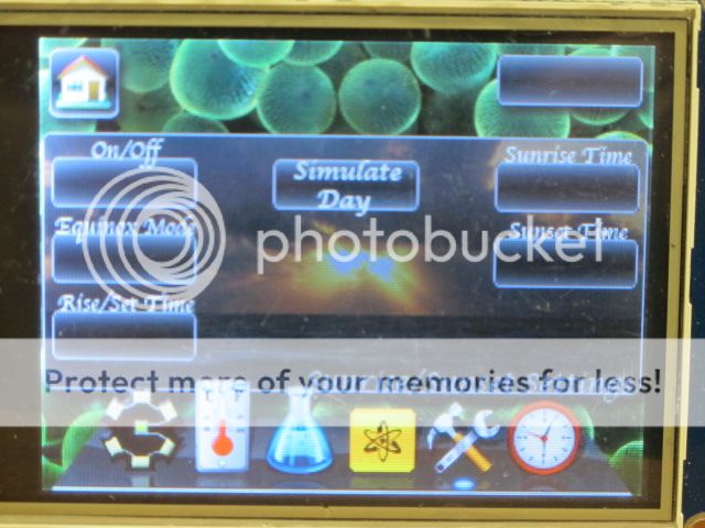
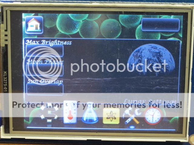
Lunar Settings.
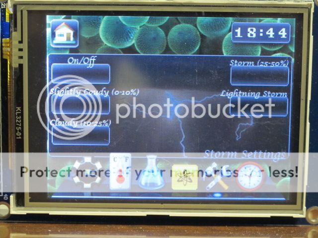
Storm Settings.
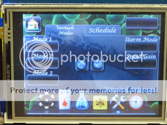
Vortech Settings.
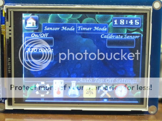
Auto Top Off Settings.
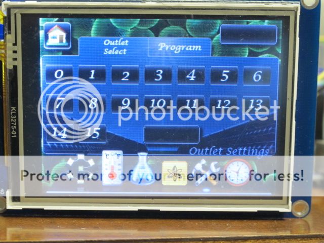
Outlet Settings (Select Outlet to view).
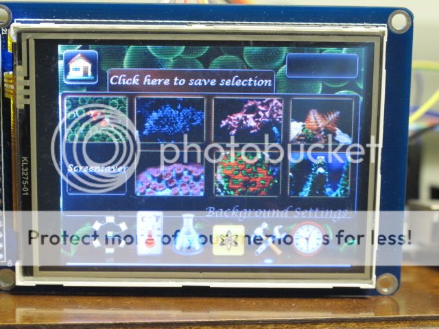
Background select.
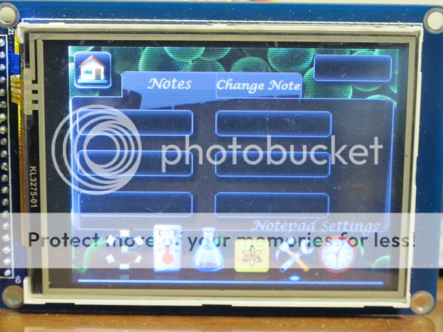
Notepad Settings(select note to view). The Title of the note will be printed on each of the buttons.
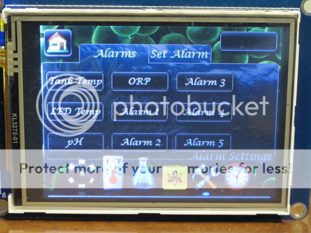
Alarm Settings. You will be able to attach notes to the alarms so that when the alarms go off, it will also popup the reminder. ex. water change, test alk, etc.
So that is the basic UI for now. I still have to create an onscreen keyboard that will popup when editing the notes. I am also going to redo the Lock screen to something a little more elegant.
Than its on to hooking up the temperature probes and 8-bit serial to parallel shift registers I'll be using for outlet control to some leds before making the outlets setup. Next step will be to add a circuit for controlling the leds.
Nick D.
Here are some shots of the new screens.
Sunrise/set Settings.
Lunar Settings.
Storm Settings.
Vortech Settings.
Auto Top Off Settings.
Outlet Settings (Select Outlet to view).
Background select.
Notepad Settings(select note to view). The Title of the note will be printed on each of the buttons.
Alarm Settings. You will be able to attach notes to the alarms so that when the alarms go off, it will also popup the reminder. ex. water change, test alk, etc.
So that is the basic UI for now. I still have to create an onscreen keyboard that will popup when editing the notes. I am also going to redo the Lock screen to something a little more elegant.
Than its on to hooking up the temperature probes and 8-bit serial to parallel shift registers I'll be using for outlet control to some leds before making the outlets setup. Next step will be to add a circuit for controlling the leds.
Nick D.
megadeth72
New member
how much memory is all of that using on the controller?
nkd5024
New member
Not sure if you mean memory on processor or the sd card for images,
As of right now, the program is taking up 58,000 Bytes of a 258,000 Byte Maximum for the Atmega2560. I am going to guess in the end it will be closer to 150,000 Bytes.
All the images on the SD card are only taking up 16.4 Mb of space of a 2Gb sd card.
btw, has anyone seen these Cree XM-L U2 Cool White LEDs they have on rapidled?
Wondering if anyone has tried them out before?
nkd5024
New member
LadyBugs,
I am currently using a sainsmart 3.2" TFT LCD Screen. I wouldn't recommend buying this brand though, instead I would recommend the Itead studio's model.
I have no problem sharing my code, although it might help if you specify what parts you want, otherwise it would take up quite some space on the forum. Once I am done, I do plan on posting the full code online with a list of parts and a tutorial for modifying the code and the UI for the way you want it to look/work.
The code still needs a lot of fine tuning to save space, etc.
Another update as of this morning, I got the three temperature sensors up and running. Two TMP36 sensors for the LED heatsinks and a single 1-wire DS18b20 for the Tank Temp.
SUPPOReefer
New member
Great thread. Definitely tagging along. I have wanted to do a project like this since I first learned about arduino; I just haven't found the time.
pulltabmike
New member
I can't wait to see this done :thumbsup: Ordering my Arduino Thursday and going to give it a whirl.
What drivers are you planning on using with your LED's? My Meanwells are hooked up to a Typhon controller, and cannot dim lower than 11%.
Mike
What part of PA are you in?
What drivers are you planning on using with your LED's? My Meanwells are hooked up to a Typhon controller, and cannot dim lower than 11%.
Mike
What part of PA are you in?
megadeth72
New member
why wont your meanwells dim more than 11 %?
pulltabmike
New member
why wont your meanwells dim more than 11 %?
I have the ELN-60-48P Drivers. According to the Data sheet, once output current drops to a certain percentage it shuts down the drivers.
Data Sheet Here
I found a DIY driver on another forum that I am getting ready to build which will allow me to dim all the way to 0
Mike
pulltabmike
New member
If you can manage to find CAT4101 chips, the triple separate PCB here on RC has worked well for me. Dims all the way to 0%.
I'm gonna give the LM3409HV a shot first.
Thanks :thumbsup:
Mike
nkd5024
New member
PulltabMike,
I am using the Meanwell ELN-60-48P as you are.
I am located about 40 Minutes NW of Philadelphia.
My understanding was that the Meanwell ELN won't drive the leds if they don't draw a specific amount of volts. So as you dim them the voltages they take decreases until the meanwell refuses to drive them anymore. For me this occurs around 25% for my white strings with only 8 cree 5w leds on them. The blue strings with 12 leds will go down to about 10 as you describe.
I read somewhere that the leds cannot dim down to 0% as they need a minimum voltage to produce any significant amount of light. Otherwise they will barely be noticeable that they are on at all, although I am not sure on what that level is at the moment, I'll look into that though.
pulltabmike
New member
PulltabMike,
I am using the Meanwell ELN-60-48P as you are.
I am located about 40 Minutes NW of Philadelphia.
My understanding was that the Meanwell ELN won't drive the leds if they don't draw a specific amount of volts. So as you dim them the voltages they take decreases until the meanwell refuses to drive them anymore. For me this occurs around 25% for my white strings with only 8 cree 5w leds on them. The blue strings with 12 leds will go down to about 10 as you describe.
I read somewhere that the leds cannot dim down to 0% as they need a minimum voltage to produce any significant amount of light. Otherwise they will barely be noticeable that they are on at all, although I am not sure on what that level is at the moment, I'll look into that though.
I'm using the 48D on my boys Biocube, and we can dim his all the way down with a 10K pot and 10V.
I'm running 3 series strings of 12 white Bridgelux, wired parallel to the controller (freshwater planted tank). Running 1 string of 12 Royal blues. Both cut off at 11%, which is still pretty bright. Controller amps set at 650ma.
Next time I take my fixture off for maintenance, I'll get some amperage and voltage readings at 11% and 100%, and compare them to my boys fixture. I'm still new to the LEDs, just built my fixture a few weeks ago. And I haven't dealt with very much electronics since the 80's lol.
I'm about 2 hours south of ya!
Mike
nkd5024
New member
Did you noticed that the leds steadily go down to off? My brother is using the meanwell D version and they also like the pwm dim to about 10% then cut off.
I think at least my issue is that the leds don't output any significant amount of light at the lower than 10% their maximum. When the meanwell don't sense enough of an electricity pull as you were talking about earlier they don't just shut off, they blink the string of lights on and off. I had this happen when I first had 4 green and 4 red 3W leds on one series string. They didn't pull enough voltage so the meanwells blinked them on and off non-stop. I added two cyan led in with them and the problem stopped.
I think at least my issue is that the leds don't output any significant amount of light at the lower than 10% their maximum. When the meanwell don't sense enough of an electricity pull as you were talking about earlier they don't just shut off, they blink the string of lights on and off. I had this happen when I first had 4 green and 4 red 3W leds on one series string. They didn't pull enough voltage so the meanwells blinked them on and off non-stop. I added two cyan led in with them and the problem stopped.
nkd5024
New member
jagr,
Its amazing what 6 months of researching on google can do huh? I still honestly feel like i'm cheating though using other peoples libraries, etc. Would love to actaully write it all in assembly, but it would take me wayyy longer to do that, so i'll stick to this for now.
6 months ago I couldn't tell you what an arduino even was.
Update:
I am planning on having all the different UI screens done by the end of the week and will hopefully be able to post a video of it running the UI. I may not have the graphing functions up and running yet though. I am going to order the SS water level sensor soon as well to start working on that as well as finally finding a way to get the outlets working.
Nick D.
LadyBugs,
I am currently using a sainsmart 3.2" TFT LCD Screen. I wouldn't recommend buying this brand though, instead I would recommend the Itead studio's model.
I have no problem sharing my code, although it might help if you specify what parts you want, otherwise it would take up quite some space on the forum. Once I am done, I do plan on posting the full code online with a list of parts and a tutorial for modifying the code and the UI for the way you want it to look/work.
The code still needs a lot of fine tuning to save space, etc.
Another update as of this morning, I got the three temperature sensors up and running. Two TMP36 sensors for the LED heatsinks and a single 1-wire DS18b20 for the Tank Temp.
nkd5024
I will wait for your tutorial after you completed your hard work.
Just PM me if you need help, I will to the best for you
Similar threads
- Replies
- 0
- Views
- 1K
- Replies
- 2
- Views
- 115
- Replies
- 6
- Views
- 2K