DIY Reef Controller

subscribing, I have no problem with the hardware portion, I just have NO idea on how to write software at all. Familiar with some code, php, some html, and good ol' DOS, but never stuck my hand into software.

Was going to go with reefangel, but with this in the mix soon, I'm holding off.
 
Will do Ladybug.

Mekanic,

I have the exact opposite problem, since all the arduino stuff comes pre-soldered and already designed for you, its kind of harder to learn the actual hardware parts as easily.

When I have time i've been going through a basic electronics class online and some of it has helped, but I still don't know as much as i'd like.

May I ask how you learned the hardware portion?

Nick D.
 
just hands on with general electronics of all kinds to be honest. I'm HVACR Contractor so relays, circuts, communicating PCB's, high and low voltage wiring are my day job haha. I only have minimal hands on experience with Arduino, having wired a RepRap for a friend.

Hobby is building PC's then paying exorbitant amounts of money to someone who knows how to write software ;) ( Damn you Bill Gates)
 
jagr,

Its amazing what 6 months of researching on google can do huh? I still honestly feel like i'm cheating though using other peoples libraries, etc. Would love to actaully write it all in assembly, but it would take me wayyy longer to do that, so i'll stick to this for now.

6 months ago I couldn't tell you what an arduino even was.

Where there is a will there is a way. I'm a software engineer but I never knew anything about Arduino or microcontrollers until about a year ago. I just started reading and reading and reading and now my eyes are open. I can't remember the last day I didn't have the thought, "I bet I could build something for that". Heck, just this weekend I was thinking of building a WiFi based Arduino with a smartphone app so I could turn on my sprinkler system without getting up. Yeah. :spin2:
 
Hello!

With a simple circuit like this image below you can dim LEDs 100-0%.

The MOSFET is a IRFZ34.

Where is DGS, read GDS.

Here's a photo of a small PCB that my friend did Baltasar.

It controls 3 drivers being 2 controlled by the same pin Arduino.

7945320072_b612ae1509_b.jpg


Best regards.
Fernando Garcia
 
mekanic,

so you build computers asa hobby? You could possible throw a nice linux distro on there to avoid having to deal with microsoft. I am an apple fan, but have recently been trying out linux mint 13 as a dual boot on my Imac.

I would love to build a reprap or a similar 3D printer. It has been on my list of things to do for a few a while now. How hard was the build?

rrasco,

I completely agree, I am alway thinking up crazy things to make with a microcontroller.


garcia,

Was that PCB created at home or was it sent out to a company?


Update:

I got the buzzer to work with the three different temperature probes. Each has its own unique "tone". I decided that instead of doing what the apex does for text input (single characters at a time pressing up and down to find the correct one) I am going to have a small on screen keyboard that will pop up when you are writing in the notepad or naming one of the 5 user defined alarms. This should make the whole experience of using the controller much nicer.

I am hoping to have the final screens of the UI done by tomorrow so then I can start actually coding all the outlet control, etc.

Nick D.
 
Did you noticed that the leds steadily go down to off? My brother is using the meanwell D version and they also like the pwm dim to about 10% then cut off.

I think at least my issue is that the leds don't output any significant amount of light at the lower than 10% their maximum. When the meanwell don't sense enough of an electricity pull as you were talking about earlier they don't just shut off, they blink the string of lights on and off. I had this happen when I first had 4 green and 4 red 3W leds on one series string. They didn't pull enough voltage so the meanwells blinked them on and off non-stop. I added two cyan led in with them and the problem stopped.

We can get the D down pretty far before it cuts off. I believe the blinking on and off issue may be the PMW frequency?

Anyway, I am ordering my boards for the DIY driver this weekend, Since the minimum order is 10, if it works out good you are more than welcome to a couple of them.

Mike
 
I have used Mint before, as well as straight Ubuntu.. I liked mint better. While it is a TON more intuitive than Linux of old, I still had not used a command line since DOS 5.0, I just could not get happy with the Terminal in Mint..

RepRap's really arent bad, the trickiest thing is the stability and making sure the platform is perfect. Gears can also be tricky to get perfect ones from someone who has printed them off unless it's dialed in beautifully. Tuning them is MUCH harder than building them. I think if I ever do one for myself it will be a Makerbot or variant.
 
Hello!

With a simple circuit like this image below you can dim LEDs 100-0%.

The MOSFET is a IRFZ34.

Where is DGS, read GDS.

Here's a photo of a small PCB that my friend did Baltasar.

It controls 3 drivers being 2 controlled by the same pin Arduino.

7945320072_b612ae1509_b.jpg


Best regards.
Fernando Garcia

all I'm using is a 2n2222 and a 1k resistor per channel and it works fine, I do wish meanwells

mine shut down at 20 %, I can use a pot to go lower but a pwm signal of 10v @ 20 % shuts them down
 
Pulltabmike,

I am not seeing how the PWM frequency could cause the blinking effect. The blinking is spaced out by about 2 seconds on than 2 seconds off. I contacted Rapidled about this issue when I started and they said it was a built in feature, which does seem a bit strange. But like I said I am no expert at the hardware aspects so any other thoughts are appreciated.

Which DIY Driver are you talking about. I am interested in looking into some different driver options, so if you don't mind I enjoy hearing about how that goes.


mekanic,

I was looking at the makerbots a little bit ago. Would love to get one of them someday, just a bit expensive as of now.

That is strange, Mine does not do that. It's gonna be a slow night at work tomorrow, I'm gonna do some googling on the Meanwells and see what I can figure out.

There is a guy on Planted tank who has made 3 different drivers which allow him to dim his leds to 0. The one I am building is based on the LM3409HV, which can handle up to 75V and 3A. For the $20 in parts it's gonna cost me, it's worth a shot.
 
Thats pretty interesting, I would like to see that thread if you have a link to it. I would be interested in trying to DIY some drivers to test out. I was just reading the DIY driver thread on here by der_willie_zur_macht, it very interesting but still a bit over my head.
 
So I figure its time for an update,

I've been busy the past week so I didn't get too much done unfortunately. I still have a few of the settings screen to program, but other than that the UI is good to go.

I did do some experimenting to see if small animations were fast enough to look good. Specifically I wanted the dock icons to bounce like in mac OSX. Since the images are stored on an SD card, it takes way to long to read them every time I need to redraw the image for the animation. And since the space they take up is too significant to store them on the chip itself, it doesn't seems like a feasible idea. Although animations with drawing shapes directly from the code is fast enough to produce simple animations. I got the bounce feature to work that way, but it obviously wouldn't look very nice with the current image based UI.

I also finally received my 12" SS Etape liquid level sensor in the main today, as well as an 8 channel Solid State relay board, and an 8 channel TRIAC mechanical relay board. After checking home depot, I realized you can just cut the piece of metal on any normal outlet that connects electricity to both outlet. This way I can control each outlet individually. Although since I don't know much about protecting them from surges, etc I still may go with a PDU. Although I would like 8 of the outlets to be individually GFCI protected, and I doubt anyone sells something like that.


Nick D.
 
This build looks awsome. I just ordered heat sinks for an led build and plan on doing a controller, think i will use your UI for a teplate. Mind if I get the code for the main screen? What are you using for drivers?
 
my led drivers are the meanwell 48-60P. Are you planning on just replicating the controller I am making or what? Depending on what hardware you use either me or you would have to change the code around. As it is right now, my code wouldn't work with a normal 3.2" touch screen. The one I got from sainsmart had the touch screen put on backwards so I had to change the code to compensate for that.

I would like to share this with people who are interested so I do plan on buying a replacement touch screen and fixing the code to reflect that. Although currently, between school, taking care of my tank, I don't have a whole lot of time, so i'm trying to get the whole thing up and running before worrying about sharing.

Once I get the whole thing running and fix most of the bugs, I will post a parts list. I would also like to test my Java knowledge (I am currently taking a java class) by making a program that anyone could download, input what hardware they are using, what pins its connected to, etc and then have it spit out the code for only what you need.

Maybe even throw together some step by step tutorials on building the circuits for the leds and outlets.
 
I would like to Replicate it sort of. Looking for a guid line on how yours was written with the background pic and menus which i really like they way they are set up. however i understand that i will have to change it to suit me anyways. I plan on using the 5" TFT. http://www.emartee.com/product/42176/TFT 5" 800*480 With SD Touch Module (Arduino Compatible). Im still new at arduino and the programing so i hope i can get it to work. Im trying to research and slowly buy the parts need. hoping i will have the tft by the end of the month.
 
I built my background and menus using photoshop. All the buttons, menus, backgrounds, etc. are photoshop created. I then converted them to raw files and saved them to a micro SD card. Using Henning Karlsen's tft lcd libraries I was able to easily read them from the sd card and do all the touch screen programming. Here is the link to his site.

http://i25.photobucket.com/albums/c54/enjoiskater158/photo.jpg

I am not sure though if his libraries will work with the 5" Touch screen you want to use. It depends on what chip is controlling the lcd screen.


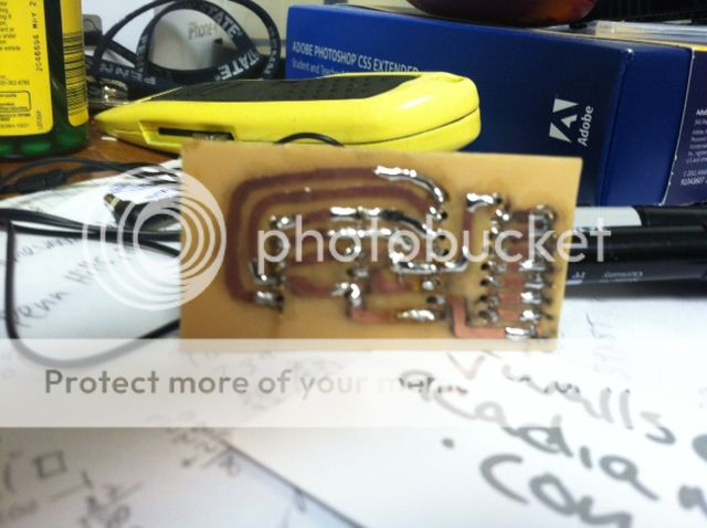
So as for progress, I spent the day testing out how easy/hard it is to print my own circuit boards. After designing an eagle file, printing it out on my schools laser printer and ironing the image to some copper clad board, it all smeared and was useless.

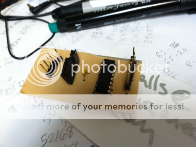
In the end I just used a high quality art marker to draw out my circuit on the copper board, threw it in a 2:1 h2o2:hcl solution, then used acetone to remove the marker. Drilled out the holes, soldered in the pieces, then covered the traces with a clear nail polish to protect it from oxidizing over time.

Here's the traces,
photo.jpg


And the soldered components,
photo-1.jpg

It doesn't look so great, but for the first attempt I don't think it turned out to bad. I have to make another replica of the same board as well as a few others in the up coming days. Hopefully I'll get better as time goes on. Btw, this board is for one of the 8-bit shift registers that will go into each of the 8-outlet relay control modules. This way I can control all 16 outlets with only 3 pins on the arduino!

Anyone going to the NCPARS frag swap tomorrow at thatfishplace, I think i remember some people saying they were from PA...

Nick D.
 
Back
Top