Silent and Failsafe Overflow System

Bean,
I am setting up a second tank with your overflow. The first one is working great and dumping water into an under-tank (in cabinet) sump. My new tank is going to have the sump in a fish room with the plumbing running through the wall. I am wondering if this system have any problems with a 20 degree run of the pipe as it exits the tank into the other room. Will this be enough for gravity to do it's thing over about 5 feet?
Thanks

Anyone? I want to go get the plumbing today hopefully.
 
The flow capacity depends on the overall head difference between the overflow and the sump it drains into. The shallow angle may or may not be an issue with the open channel, depending on flow.

20 degrees over 5 linear feet is a drop of about 1.82 feet....

Does that sound right or am I not understanding what you are setting up.
 
Need plumbing recommendation

Need plumbing recommendation

Hello,

Thanks everyone for the excellent thread. I've read all of it, including the posts a few pages back about what to do with a pre-drilled tank.

I too have a pre-drilled tank with an internal coast-to-coast overflow. The tank is 37" high, so I have very tall standpipes inside the overflow. The weir is 20" wide.

I have two 1" holes and two 2" holes in the bottom of the tank inside the overflow (which was a mistake; the latter were supposed to be 1.5").

So: what kind of overflow would everyone recommend? Obviously a Herbie is straightforward, but after reading the entire thread, I'm leaning toward Beananimal. This would require some hacking, given the 4 holes I have.

I could really use some advice about what will work best, what mods I need, and what problems I'm likely to run into.

One other thing: my sump is 10 feet below, in the basement.

thanks!
Brian
 
Bean or anyone with a multi tank basement sump configuration "“

I am looking into putting together a system with a 60g cube on the main level with a 110g and a sump in the basement. I want to use the 3 pipe Bean overflow from the 60 into the 110, and from the 110 into the sump. The return pump would go back up to the 60.

As stated above, the 60 would drain into the 110. The 110 will be eurobraced with holes drilled in the rear corner bracing. I would like to use LocLine to direct the flow on the drains into the 110g. Is that going to create problems?

The 110g will also use the Bean overflow and I would like to feed my skimmer from one or several drains. I've read on this thread of people trying that, but I wasn't sure about the success rate or any caveats involved.

Neither tank is built yet, and I'm still in the design / research phase so any input would be greatly appreciated.

Thanks for keeping this thread going for so long!!!
 
LoneRanger:

You asked how to support the standpipes in your setup
n743521451_1302716_4322.jpg


Here is the easiest way to do it. The velcro straps are attached to the brackets with epoxy (screws could be used instead).
75-Gallon-Equipment-Rack.jpg


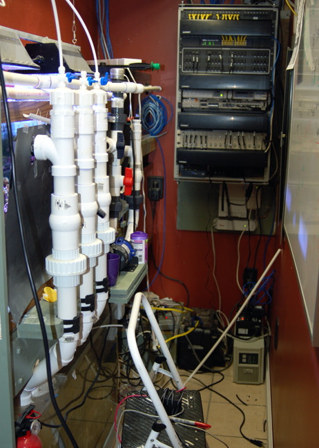
Savko, and others also sell plumbing support brackets that could be fitted to a wood extension.


Is that an ABB Freelance in the background?
 
Scott26, yes, the standpipes will be the full height of the internal overflow, or I can cut them to any length.

Brian
 
Is that an ABB Freelance in the background?
75-Gallon-Equipment-Rack.jpg


Nope... That is not quite complete fish room that is more complete now, but still a mess :)

Rack: Top to bottom
  • 24 Port Hubbell Cat6e patch panel - terminate network drops to each room of the home
  • Ortronics cable management panel
  • 24 port POE switch - the backbone of our network
  • 48 Port Ortonics RJ-21 patch panel - terminates household voice jacks and dial tones (home, business, etc)
  • Ortronics cable management panel
  • Partner ACS messaging 6.0
  • Partner ACS 7.0 business telephone system (runs both household and business lines)
  • 32 Port BNC patch panel - terminates RG6 cables drops to each room. Used for TV distribution.
  • Ortronics cable management panel
  • Power Distribution center
  • Verizon FioS battery backup and PSU (mounted just below rack)
Not shown (in rack) DirecTV multiswitch, 66BLock for copper from outside (cross connected to Ortronics voice panel). Cisco 871W router.

Below the rack on floor, White Liebert GXT 700VA UPS (powers phone system).

Black box to the left, deep cell backup battery for sump pump.

The UPS has since been upgraded with additonal battery cabinets so that I can get about a day of runtime out of the phone system and network switch during a power failure. The phone system has also been switched out for an Samsung OfficeServ 7100. (I sell both the avaya and sammy and figured I would give the sammy a try).

Not seen in the photo is the pile of Liebert UPS cabinets that keep my server running during power outages. One of these days I will install a standby genset. If you guessed that I am a Liebert VAR, you would be right too :)

There is another "rack" adjacent to my home theater that also holds a switch, and the switch gear for the home theater, the AV equipment for the HT and whole house audio system (SONOS) along with a patch panel for all of the speaker runs.

None of the aquarium electronics are seen in that photo either.

And who said bean lives in the stone age?

;)
 
Scott26, yes, the standpipes will be the full height of the internal overflow, or I can cut them to any length.

Brian

If you are going to do a coast to coast I would recommend a drilling the back it would be the easiest as far as your current set up goes I am not sure I understand so maybe someone else can chime in.
 
Thank you for the design.

I fired mine up 3 days ago on the very first time it was problem free.

I am completely happy with it.
 
Bean or anyone with a multi tank basement sump configuration "“

I am looking into putting together a system with a 60g cube on the main level with a 110g and a sump in the basement. I want to use the 3 pipe Bean overflow from the 60 into the 110, and from the 110 into the sump. The return pump would go back up to the 60.

As stated above, the 60 would drain into the 110. The 110 will be eurobraced with holes drilled in the rear corner bracing. I would like to use LocLine to direct the flow on the drains into the 110g. Is that going to create problems?

The 110g will also use the Bean overflow and I would like to feed my skimmer from one or several drains. I've read on this thread of people trying that, but I wasn't sure about the success rate or any caveats involved.

OK... read read read... I figured these questions have been answered somewhere in here, but I couldnt find anyone doing a tiered tank system with it. That being said, I have deduced the answers to my questions from the responses to others... but anyone can chime in with feedback if they want.

I will have my 1st floor Cube tank drain both the siphon and open channels into the basement 110 using the traditional BeAn method. These two drains will enter the 110 thru holes drilled in the euro-bracing. I will use a 45 degree elbow and LocLine below the euro-bracing to direct the flow. The caveat will be to keep all this plumbing below the euro-bracing a couple inches below the surface of the water. A bulkhead + 45 + Locline could end up deeper in the water column than the design allows for, and therefore be something I need to work out on a trial and error basis. As of now, I am going to assume that the LocLine will provide some of the restriction that the ball/gate valve is designed to do. The key will be in keeping it submerged but not too deep in the tank. The 3rd emergency siphon will drain directly to the sump.

The 110 will again use the 3 pipe BeAn. However, I will tee off my siphon from the 110 and use a ball or gate valve to regulate flow to my recirc skimmer. The open channel will drain into the fuge section of my sump while the remainder of the siphon will dump into the opposite end of my sump. Again, the 3rd emergency siphon will drain directly to the sump.

Coincidently, I am planning to have 1.5" overflow drains on my sump, RODI, ATO, and water change reservoirs (all of which are automated). All of these will dump into a mop sink and if the mop sink overflows it will spill onto an epoxied concrete floor which slopes toward a floor drain"¦ if the sewer also backs up"¦ well"¦ I'm screwed.
 
It would take 6 months, to do justice to this design. But short and sweet: drop your drains from the display tank, to whichever tank contains the return pump. Drop the drains clean, (no lock line,) into this tank . Place the skimmer (behind baffle) in the same tank, with the return pump.

Feed the 110 via the return pump, and use the beananimal out of the 110. This way you won't have a balancing nightmare. This makes two "display" tanks with a common sump. Much more functional. Feed any other accessories via the return pump (like your "fuge")

Drop drain lines into the same "chamber" not the siphon in this one, and the open channel in that one, and follow the design criteria of not more than 1" below the surface of the water. You will have a great deal of head pressure, with the long drop to the basement, but still follow the criteria. Bean has mentioned this several times for long drops: Put the siphon valve down close to the sump.

I am not aware of anyone gravity feeding a skimmer with the siphon using bean's system, so the results are unpredictable. It could mess with the start/restart of the system.

System design should be simple, straight forward, but also reliable. I see the nuclear power plant you are designing be a balancing nightmare. You will need a larger pump, but you will have far fewer headaches. The more complicated the plumbing, the easier it is to stop up the drain.

Jim
 
Last edited:
Jim - By all means thanks for your comments. I truly do appreciate anyone interested in my system and offering advice for the sake of it. I know that you have been involved in this thread for quite some time and I trust what you have to say is based on knowledge and experience... the reason I am posting is to avoid exactly what you are thinking will happen...

I see what you are saying in that I should run the 2 displays independent of each other sharing a common sump... and in many ways it makes perfect sense, especially if any other way won't work.

Without offending, I was wondering if I could elaborate a little on the design; tell you why I thought it would work and we can go from there.

Tank #1 is a 66g Cube(ish) on the 1st floor of the house with external shallow (5-6") overflow running the width of the tank. The overflow would have 3 "“ 1.5" bulkheads in it. The tank would also have 2 return bulk heads but that matters little in this discussion.

Tank #2 is a 5' 110g in the basement directly below Tank #1"¦ straight shot, no bend or anything. I'm going to leave LocLine out of this completely for now, so let's assume that the siphon and open channel both just terminate under the water line with a 45 elbow.

Now the sump is also in the basement"¦ behind the 110"¦ in a sump room. The 110 drains into the sump (let's forget for a moment about feeding the skimmer, but we will revisit it later) using the BeAn method again. The return pump which will draw from, but be external to the sump, will pump back up to Tank #1 on the 1st floor exclusively.

Ok here's my thinking"¦ whatever is being pumped into tank #1 from the return pump will drain through the overflow and be balanced using a gate valve. In turn, whatever is being dumped into the 110 will pass through the overflow as well and be balanced by a gate valve. So let's say that 600gph goes from the sump in the basement through the return pump and into tank #1. It would make sense that 600gph goes through the BeAn overflow and into the 110, and that 600gph would again pass through the overflow of the 110 and into the sump.

I am not disagreeing that the system will be balanced in 2 places. However, it has been stated that the system is self balancing over a wide range (forgive me here, because I cannot seem to use the "œquote" function of the RC forum on a portion of the thread that has been closed due to being split). So I figured that as long as I'm not on the threshold of the overflows' capacity the system could be balanced and remain balanced over a wide range. I know over time the return pump flow will not be constant, but still the system should compensate, right?

So this is where I need help explaining why this would work.

OK part II"¦ Feeding the skimmer from the siphon.

I feel like I'm gonna get banned or something here. Again, I can't quote because the first part of this thread has been closed due to being split. But it was stated on pg 31 post 761 dated 10/6/2008 that others had been successful feeding the skimmer with the siphon, and I believe it was in reference to the suggestion of using a T in the siphon with a ball valve to regulate the flow to the skimmer.

Of course, that was said almost 2 yrs ago and the test of time may have disproved that. If it's been tried and just plain doesn't work, I'll accept that as an answer.

But help me out with first one please.

One final note"¦ I apologize in advance if this really way off topic and I should have found a different thread to post in or started a new one all together. However, I truly thought the BeAn overflow would really make the tiered tank system work.
 
Jim - By all means thanks for your comments. I truly do appreciate anyone interested in my system and offering advice for the sake of it. I know that you have been involved in this thread for quite some time and I trust what you have to say is based on knowledge and experience... the reason I am posting is to avoid exactly what you are thinking will happen...

Factual stuff, leavened with a little bias and opinion, based on experience. I am not infallible, even if it is thinking one word and typing another, or typing what I am thinking at the moment, rather than 30 seconds ago, or vice versa.

I see what you are saying in that I should run the 2 displays independent of each other sharing a common sump... and in many ways it makes perfect sense, especially if any other way won’t work.

Makes perfect sense even if another way would work, and in my view the best way. Many see this Socratic part of me, one even called it a Socratic attack.

Without offending, I was wondering if I could elaborate a little on the design; tell you why I thought it would work and we can go from there.

Tank #1 is a 66g Cube(ish) on the 1st floor of the house with external shallow (5-6”) overflow running the width of the tank. The overflow would have 3 – 1.5” bulkheads in it. The tank would also have 2 return bulk heads but that matters little in this discussion.

Tank #2 is a 5’ 110g in the basement directly below Tank #1… straight shot, no bend or anything. I’m going to leave LocLine out of this completely for now, so let’s assume that the siphon and open channel both just terminate under the water line with a 45 elbow.

Now the sump is also in the basement… behind the 110… in a sump room. The 110 drains into the sump (let’s forget for a moment about feeding the skimmer, but we will revisit it later) using the BeAn method again. The return pump which will draw from, but be external to the sump, will pump back up to Tank #1 on the 1st floor exclusively.

Ok here’s my thinking… whatever is being pumped into tank #1 from the return pump will drain through the overflow and be balanced using a gate valve. In turn, whatever is being dumped into the 110 will pass through the overflow as well and be balanced by a gate valve. So let’s say that 600gph goes from the sump in the basement through the return pump and into tank #1. It would make sense that 600gph goes through the BeAn overflow and into the 110, and that 600gph would again pass through the overflow of the 110 and into the sump.

I am not disagreeing that the system will be balanced in 2 places. However, it has been stated that the system is self balancing over a wide range (forgive me here, because I cannot seem to use the “quote” function of the RC forum on a portion of the thread that has been closed due to being split). So I figured that as long as I’m not on the threshold of the overflows’ capacity the system could be balanced and remain balanced over a wide range. I know over time the return pump flow will not be constant, but still the system should compensate, right?

So this is where I need help explaining why this would work.

I would think that if anything has a chance of working as expected, it would be bean's system. I still would not do it. There was a reason I said it would take 6 months to do justice to this system: I would have to build it, test it, and go from there. Factual stuff: I have never had one of these type systems work worth two hoots in the netherworld, unless set up as I described. Bias: I wouldn't do it. Plumbed to a common sump is more manageable. What are you going to do if you have to stop flow to the middle tank for any reason-- for an extended period of time? You have to shut the whole system down and re plumb. With a common sump: turn a valve and it is done. The same line of thinking goes for all accessories. Opinion: A nightmare.

OK part II… Feeding the skimmer from the siphon.

I feel like I’m gonna get banned or something here. Again, I can’t quote because the first part of this thread has been closed due to being split. But it was stated on pg 31 post 761 dated 10/6/2008 that others had been successful feeding the skimmer with the siphon, and I believe it was in reference to the suggestion of using a T in the siphon with a ball valve to regulate the flow to the skimmer.

Of course, that was said almost 2 yrs ago and the test of time may have disproved that. If it’s been tried and just plain doesn’t work, I’ll accept that as an answer.

I included that post below. I have not tried it, and I am not certain, but I don't think bean has either. I have not yet SEEN that anyone has done it. I mentioned one POSSIBLE repercussion. For me, it does not make sense, I don't believe in messing with drain lines. The system works as designed, and has a great deal of flexibility. However, I won't endorse modifications unless I see repeatable success. It would seem easy, to test this stuff, but the system has to work the first time I throw the switch. I don't have the luxury of re plumbing. I stick with and recommend what I know will work the first time-- every time.

However, this is bean's baby, not mine.

But help me out with first one please.

One final note… I apologize in advance if this really way off topic and I should have found a different thread to post in or started a new one all together. However, I truly thought the BeAn overflow would really make the tiered tank system work.

NOTE: This quote differs from the original in the following ways: 1) Clicking on the arrow next to the posters name, will not link to this post. 2) The content of the post has been altered to correct a couple typos for clarity. No other changes have been made. The context is unaffected.

You can use the 1.25 inch plumbing if you like. There should not be that much difference. Bigger is always better for the open channel though. All three drains should lead to the intake compartment of the sump, you could however, send the open channel to the refugium and/or tee off the siphon to the skimmer. Some people have used part of the siphon flow to feed a skimmer with success, though I have not tested it.

Jim
 
Last edited:
Very good points. The 2 best of which is probably that it should be built and tested prior to any endorsement, and having to stop flow to the middle system could pose a big problem. It definately lacks the flexibility and managability that the system you described has. Many things in this hobby are "go with what works" for a reason.


Hey man, thanks for taking the time to expand on this.
 
Alright guys, I love this drain! I've got a question for everyone. I've set up my drain and didn't give much thought about were the drains terminate in the skimmer chamber. The siphon and secondary drains are pretty close the the first baffle in the skimmer section. Do you guys think this matters? After staring at the sump for a minute, I think I would like the pipes in the corner furthest from the baffles. Here's a pic of the setup now. The pic is of the back of the sump.
ea70c5d7.jpg~original


I don't feel like cutting an splicing the pipe, plus this thing works perfect. It starts right up after I simulate a power failure. I'm afraid that if I mess with it, I might not get the same results. So... Leave it, or change it?
 
Last edited by a moderator:
Back
Top