Silent and Failsafe Overflow System

I have a 100 gallon tank with a built in overflow I am trying to modify for this system. The drain section is small, and I'm having to drill holes creatively to fit the siphon and open stand pipes in the overflow box.

Is there an issue with having the emergency pipe in the tank?
I know that it would only take on water if the dt water level rises, but I think it would still work if it had to. I'm wondering how it would affect the system at startup, possibly hindering the full siphon starting on the main pipe?

Thanks!
 
There are no holes in the bottom of the overflow?

The BA does not lend itself well to small overflows such as this, and it is not recommended that you use it. The Herbie modification is better suited for it. (siphon and dry emergency.) You are pretty much stuck with that if the tank is acrylic, though these small overflows aren't sufficiently sized for the tank in the first place.

A better plan on a glass tank, is to remove the overflow, plug any existing holes, build a L shelf overflow at the top of the tank, drill out the back for a BA system.
 
Can I run a manifold off the siphon? I would ideally like to run my skimmers and other equipment/reactors from the return to sump line.

I would also run a submerged line into a filter sock from the manifold to keep the siphon quiet and dump any excess water into the sump not used by equipment.

Is this possible or does it need to be a straight shot to the sump from the overflow?

NO. It will mess with the operation of the system. Bad idea. Bite the bullet and do it right. Straight shot to the sump. Run the skimmer on its own pump, and run whatever else you feel you need from a tee in the return line. (The return goes from sump back to the tank. The line from the overflow to the sump is called a drain. :) )

Filter socks, and any form of mechanical filtration really do not have a place in marine systems. That is a carry over from freshwater systems, as what we are concerned with in marine systems, cannot be removed by mechanical filtration. (The skimmer is actually a mechanical process, however lets not confuse the issue.)

Send any "excess" water back up to the tank, via the return pump. That is where it is needed. Dumping water back into the sump is a huge waste. Though what you are saying is not all that clear.
 
Cheers for the reply uncleof6,

Yup, I thought that might be the case. I was just trying to capture the waste/drain from the display straight to the skimmers so they get a straight shot at the dirty water.

Not much difference but the less pumps running the lower the cost of equipment, lecky, noise and things to go wrong.

I'm not sure I agree with the filter socks though. I've run a large system before and there is always some larger particles that a sock would be best at removing. You do have to keep on top of maintance as you don't want waste staying in the system. But it's either a case of siphoning them up or catching them in a sock.

Or, keep the flow rate high enough that particulates are kept in suspension, where they are utilized as a food source for your critters. I could feed you a bunch of anecdote about the 250 or so systems I have running without any form of mechanical filtration, and how much of a mess I would be in with clients, that have way more money than I, if the systems were loading up with crud. I would much rather say that on the whole, maintenance is neglected with socks, and skimmers as well. It is a tiresome chore to change the socks every day, and clean the skimmer every week. We all would like to reduce the husbandry end of the hobby, but unfortunately, there is no way around it.
 
OK Uncle, I think I've settled on what I can do. Instead of going with a standard 6x2x2 180, I can do a 60"x28"x24" - I need to be able to get the stand through the doorway or else I would go wider.

I don't care for the esthetics of an internal weir across the back of the tank, so I'm planning on putting the drain on the side of the tank. I had hoped to do this external, but ran into the problems as previously described.

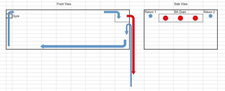
So as a compromise, I am thinking of an internal box that is 24" wide. This will allow me to run returns on either side (hopefully) as depicted in the image below. The returns would point down on either side of the weir, and assist in creating a circular flow that directs surface water back towards the weir.

The question I have now is how large to make the internal box and the placement of the 1.5" drain holes/bulkheads in relation to the box.

Your help, as always, if very much appreciated.

Paul
 
ImageUploadedByTapatalk1424366087.197362.jpg
 
Probably thousands have done an internal without teeth. Calfo's C2C has been around for a long time. I have done a couple three hundred, if I have done one.

Since you have not made the decisions you need to make, before building this thing, you are getting way ahead of yourself. You need to pick a flow rate, 10x, 100x, XXx... you need the length of the drop, to figure out the drain sizes, you need a return plumbing configuration to do the friction loss calcs at that flow rate, to figure out what pumps you can and can't use. You should not think about buying anything or cutting any holes, before the paperwork is done. :)

OK Uncle, I think I've settled on what I can do. Instead of going with a standard 6x2x2 180, I can do a 60"x28"x24" - I need to be able to get the stand through the doorway or else I would go wider.

I don't care for the esthetics of an internal weir across the back of the tank, so I'm planning on putting the drain on the side of the tank. I had hoped to do this external, but ran into the problems as previously described.

So as a compromise, I am thinking of an internal box that is 24" wide. This will allow me to run returns on either side (hopefully) as depicted in the image below. The returns would point down on either side of the weir, and assist in creating a circular flow that directs surface water back towards the weir.

The question I have now is how large to make the internal box and the placement of the 1.5" drain holes/bulkheads in relation to the box.

Your help, as always, if very much appreciated.

Paul

If you run the returns over the top you will improve the surface skimming somewhat and also make the installation easier.

As to the dimensions, you need to plan it out - Sketchup or a similar layout tool is helpful. Some general guidelines:

Hole spacing - minimum of 1 hole diameter between glass edges. i.e. if you are drilling a 2" hole, the edge of the hole needs to be minimum 2" from the top or side edge of the tank glass and 2" from the edge of any other hole. I posted a drawing here

Measure your bulkheads and the flange. By the time you have the holes far enough down so the flange clears the tank trim you frequently have met the hole to tank edge requirement.

Allow about ¾" under the elbow and enough room between the front edge of the elbow and the vertical overflow wall to get your hand in.

If you are planning on using threaded elbows, allow enough space to unscrew them if you want the ability to easily disassemble the system.

The top edge of the front overflow wall determines the water height in the tank; most people put this even with the bottom edge of their trim.

Beyond this, you need to measure the components you plan on using and space things accordingly.

Thanks Sleepydoc.

I don't plan on using a canopy, so I was trying to avoid running the returns over the top if possible. I understand that I will lose the 4" of surface skimming, but I'm trying to compromise where possible.

If I use a 24" wide weir/internal overflow box, that will leave 2" on either side of the box for the returns. With this configuration, I could use 3/4" returns on either side of the overflow box and leave 1" between the edge of the glass pane and still have 1/4" between the hole and the box. I will have to double-check the flange of the 3/4" bulkhead to see how much room I need.

I should then be able to easily spread the 3 BA holes (1.5") over the 24" of the side pane that will be in the overflow box.

Does this make sense?

Also, the side and bottom panes will be tempered, if that makes any difference.

You will have plenty of room for the overflow holes, but you will need more than 2" for the returns. The hole size for a 3/4" bulkhead is approx 1 3/8". Accounting for the bulkhead flange you'll need at least 3" on either side.

The plastic trim doesn't matter - it just gives a natural place to put the waterline if you have it. You still need to keep the holes a minimum of 1 diameter away from the nearest glass edge, preferably 1.5 diameters.


Thanks Sleepydoc.

So should I let the builder just put the holes where they need to be and them make the overflow box as large as possible afterwards? Or perhaps drop down to a single return? It seems that it would be more balanced to have dual returns.

Also, how deep does the box need to be to prevent the drains from cavitating?


Anyone know how deep the box needs to be to avoid cavitation on a 1.5" drain?
 
Thanks Sleepydoc.

So should I let the builder just put the holes where they need to be and them make the overflow box as large as possible afterwards? Or perhaps drop down to a single return? It seems that it would be more balanced to have dual returns.

Also, how deep does the box need to be to prevent the drains from cavitating?

You need to determine where the holes need to be, based on your mockup of the system. The glass companies are notorious for getting it wrong, don't know where the holes need to be, nor do they care. You have to tell them exactly where they need to be, and if they miss, it is up to them to fix it (usually replacing the tank.) This isn't rocket science, so a little variation is not the end of the world.

Again, it depends on where the holes end up. The box needs to end ~3/4" or so, below the bottom of the down turned elbows. If using an external box, it will have to be taller, to allow some vertical adjustment for tweaking the system. Number 1 mistake for commercial and DIY boxes is they are too small. "It works fine" does not begin to say anything.


Thanks Uncle, that's what I wanted to be clear on. I will work out the math in a sketch and post it here for review. I want to have the returns as high as possible on either side of the internal overflow box/weir, and will have to take into account the flanges.

For 1800 gph on the return, can I go with 2x 3/4" returns or do I need to move up to 1"?
 
When I sketch this up, it appears that I would lose too much of the side wall to the spacing required to have the returns go through the side wall. As much as 10" would be taken up to accommodate a 1" bulkhead and flange on either side of the weir/box. This would effectively reduce the overflow to 18" maximum, which IMO would negate the surface skimming benefits of the system. So I think I would be better off making the internal box 24" (of the 28" total tank width to accommodate the returns). Then, I can have the return holes drilled through the eurobracing in the corners (unless this is a bad idea). This way, I can run the returns up and over the same side as the drains/box and back through the Eurobracing pointing down (1 hole in each corner) to aid in maintaining a circular flow.

Does this make sense?
 
Run the returns over the top, and you only need one of them. Let your power heads do their job.

What size you run for the RETURN, depends on the output size of the pump. Return pipe should be one size over the output size, minimum. It should not be split or otherwise reduced in size.

When you get your sketches done, it would be better to start a new thread, overall system design is off topic for a drain system thread. :)


Fair enough. For the drain holes, is there any advantage to having the full siphon hole lower than the other two holes?
 
Back
Top