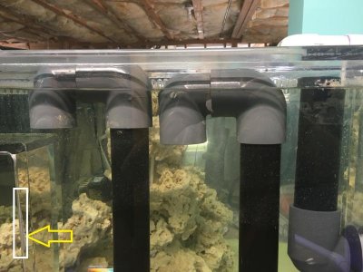
Silent and Failsafe Overflow System

thanks a ton everyone, i need to tweak it and see how things go. I'll drill the siphon line hole and install the fittings and move things down a bit.

the hole is only drilled in the open channel/trickle line (the taller standpipe with the double-90s), NOT the lower siphon line (the lower pipe with the double 90s)
 
If you leave everything unglued in the box, make sure that your sump can handle the volume if the entire volume of the box drains down.

Also, be aware that for the siphon channel any unglued joints may let air in and either cause noise or interfere with the siphon. (This isn't a given but can happen depending on your fittings


Sent from my iPhone using Tapatalk
 
yes, i didn't want to drain the entire overflow on shutdown.

What do you mean by vertical seam? an issue with my tank or how the pics appeared on the page?

attachment.php
 

Attachments

  • rc-seam.jpg
    rc-seam.jpg
    63.1 KB · Views: 0
I purchased an overflow box for my new build, a 5ft 120. that is pretty much a clone of the synergy reef overflow. The external box utilized 3 1" bulkheads to drain to the sump. The internal box doesn't look like it can fit 1 1/2" fittings, maybe 1 1/4". Would it benefit me to use 1 1/2" plumbing after the bulkheads? Does it make a difference? Thanks
 
The maximum flow capacity is determined by the bulkhead size, and the amount of head height (water level to water level.) The pipe size determines how much friction loss will reduce the flow capacity from the max theoretical capacity. The larger the pipe size, the less friction loss, and consequently the higher the actual flow capacity.

At the other end, to actually get any benefit from a drain size increase, your pump and associated return plumbing need to be capable of returning more than the capacity of 1" pipe at the same head height, which would be ~ 1200 - 1300gph depending on head height. Large pipe, when not needed, makes it more difficult to purge the air out of the system.
 
Return pump is about 1500 gph at 0 head. I used the head loss calculator and the calculated output was about 750gph. I think i'll be fine with 1" through out.

Thanks for your input,
 
That would tell me the pump is too small for that tank, which would run better @ 1000+gph, with 1200 gph being a good target. I suspect that with a little "engineering" in your return plumbing, you can get the flow rate up... unless you have an abnormally high head height...
 
I'm confused - what fittings do you need in the internal box? I thought the synergy was a thin internal box coupled to a external box that had all the plumbing.

In any case, Uncle is mostly right. Plumbing resistance is additive, so while the majority of the resistance will come from the bulkhead, upsizing the pipe/fittings before and after the bulkhead will give a nominal decrease in resistance to flow. Whether it is significant depends on the specifics.

A 1" siphon ought to be able to handle your needs quite easily. If you need a small amount of extra wiggle room, you can trim the end of the fittings and get an extra ¼~½"

What kind of pump are you using?
 
I'll be using a Jebao DCT 6000 which is rated at 6000 lph or 1585 gph max at 11 feet head. I don't have the pump in front of me but it comes with a 1 1/4" hose fitting. I'm not sure what the output size thread is on the volute, but I'm guessing its a metric size. The pump is being delivered today. My intent with plumbing was this:

Pump to 1 1/4" hose to 1 1/4" tee reduced at both outputs to 1", then up and over the rear wall of the tank with multiple 90s.


Sorry about that, I meant the external box. You are correct in how what I have is designed.

I'm not really worried about getting the maximum amount of flow through, but really more worried about it being balanced. Even though this isn't going on a saltwater tank I would like the design to be as correct as possible.
 
Jebao DCT-6000 input: 1.25" MPT; output: 1.25" MPT. Well, that is what it says... MPT = Male NPT. I don't try to explain chinese instructions, or why they use NPT for larger pumps, and MPT for the smaller ones... one says FPT (Female NPT.) NPT is generic: NPT = National Pipe Thread Tapered...

Max head is 12.5'.

Balance: Water out = water in, regardless of circumstances. At a 24" drop, a 1" hole will flow ~1666gph. With 1" pipe, friction loss could be as high as ~25%. @ a 36" drop, it would be 2041gph. Friction losses would be around the same (25%.) A few variables involved, so it could be more or less.

Looking at how you plan the return, your actual flow will probably be <1200gph, easily. (tee and many elbows + extra pipe + static lift.) I don't really see any problem in the future with 1" pipe. But even if such did occur, the system is adjustable at both ends (pump output/drain valve) so it could be easily balanced, considering you are not really concerned with maximum flow rates. But without specifics, it is not really possible to mathematically determine how the system is going to behave. Generally pump/drain systems are "engineered" with a specific flow rate target, and then calculations are done to determine what pump will do the job. Going the opposite direction, is pot luck.
 
Thanks for the information.

One last comment, I have scoured over the variation of designs and photos of other tanks and the heights of everything and I couldn't find a simple answer as to the height relation between the internal weir, the external 90s for the siphon line and open channel. I don't know how critical all these measurements are, or if it is just the basic design that needs to be followed and they all achieve the same result. Which is a reliable, fail-safe silent overflow. I guess this really just takes experimentation and testing for my particular setup.

The relationship between the top of the weir, and the elbows is simply how far will the water fall into the overflow box. (It is noise related; the goal is to get around 1" or so. It has no relevance to the operation of the system. What is more important is how far down the top of the inlet to the dry emergency is from the top of the tank... 1" +.
 
Thanks for the information.

One last comment, I have scoured over the variation of designs and photos of other tanks and the heights of everything and I couldn't find a simple answer as to the height relation between the internal weir, the external 90s for the siphon line and open channel. I don't know how critical all these measurements are, or if it is just the basic design that needs to be followed and they all achieve the same result. Which is a reliable, fail-safe silent overflow. I guess this really just takes experimentation and testing for my particular setup.

honestly, what's most important IMHO, is making sure the water level sits high enough in the tank, and that the box is set correctly in that regard. The external box adjustments are a cakewalk!

1" PVC inside the external box is probably fine. I know you see lots of advice to upside it, and I do prefer to do that when I can, but it's really more of a noise thing than anything, and yes eventually friction as well, but this is only a problem if you're up against the wall in terms of the drain's capacity. If you've got the capacity and all that - you'll be fine. And I can tell you - as someone who runs a DC-6000 on a herbie with 1" drains (on another tank), you'll be fine.

In fact, let me show you how I did mine (as I also have a ghost-style overflow, from modular marine in this case)

http://www.xero.cc/fish/120_overflow_exterior.jpg
http://www.xero.cc/fish/120_overflow_exterior2.jpg
http://www.xero.cc/fish/120_overflow_exterior3.jpg

It's somewhat difficult to see, but the siphon is simply a strainer, one of these:
https://www.amazon.com/Lifegard-Aquatics-Profile-Strainer-R441012/dp/B00CRIDNV6

The open channel is just 2 90s with a hole in the corner. I ended up cutting the pipe so that it sits as high as it can before hitting that center brace. It's definitely a manuver to get it in there.

trying to fit 2 sets of double-90s inside the external box is often a challenge, and totally unnecessary. An added benefit of using a strainer is that the external box will drain almost entirely when the pump shuts off, which is nice for cleaning and such.
 
Thanks for the input. Pump came in yesterday, so I'll be filling and tuning sometime this weekend. I'm sure I'll be back with some more questions and need of some more insight.
 
WHOOP!!!!! Finally got my tank filled for it's first water test.

Beananimal works awesome! First time... perfect. Couldn't be more pleased.
 
Hi. I got a tank with 2 overflows and 3 bottom drilled holes. There's PVC threaded in already with open top. I'm planning to turn it into BA. the PVC are dif length but that can be fixed.

Question is, does the order of the pipes matter? I need to keep the emergency on the dual pipe overflow. Which pipe should I leave as full siphon and which one open channel?
 
Last edited by a moderator:
*Removed*

You should have the siphon and the open channel on opposite sides.

I would probably do siphon/emergency on the double side, and open channel/trickle on the single side. You don't want the emergency by itself or else water will go stagnant in there. You could put the siphon by itself and put the trickle/emergency together, too. It really doesn't matter. I'd do it whatever way creates the shortest and most direct plumbing runs.
 
Last edited by a moderator:
Back
Top