Silent and Failsafe Overflow System

Here is how I am going to set up my Bean Animal system./

Here is how I am going to set up my Bean Animal system./

I would drill as many as I can fit into the width of the box. On my tank it was done that way opposed to being grooved and I notice that the box doesn't get as much water as the siphon can handle which causes me to have less turn over then I want.

I just bought the Synergy 20'' external overflow box for my new 150 display that I am currently building. Here are few pixs! The only thing that I glued are the 1.5'' unions and then I will reduce down to 1'' for the bulkheads on my sump. For my returns I will be going 1'' and reduce down to 3/4'' locline. The last picture will be the way I hard plumb my system with Wye Check Valves
 

Attachments

  • IMG_6105.jpg
    IMG_6105.jpg
    56.1 KB · Views: 0
  • EXTERNAL OVERFLOW BOX INSTALL.jpg
    EXTERNAL OVERFLOW BOX INSTALL.jpg
    46.1 KB · Views: 0
Hole Location

Hole Location

Hello Beananimal,
I am going to be setting up a 125 gallon Mezzo tank soon and would like to incorporate the Beananimal design. The mezzo tank already comes with an internal overflow in the middle with a 1 1/4" hole at the bottom. I would like to use the 1 1/4" hole in the bottom as my Siphon Standpipe and would like to drill two additional holes from the rear into the overflow to act as the Emergency Standpipe and Open Channel Standpipe. Since my hole drilling from the rear will be permanent, I want to make sure they are in the correct location. I have included three images below that show what I am talking about. Could you please give me some feedback. Thank you.
 

Attachments

  • Tank Front View.jpg
    Tank Front View.jpg
    47.3 KB · Views: 0
  • Tank Rear View.jpg
    Tank Rear View.jpg
    96.3 KB · Views: 0
  • Tank Bottom View.jpg
    Tank Bottom View.jpg
    27.4 KB · Views: 0
not trying to hi-jack thread but I have been running the bean silent drain for years same setup, tank nothing changed and it has done great but yesterday I noticed that I get no water down the main drain (one with the valve) and my water is coming down the secondary pipe. To keep from going full siphon I have slowed return pump output and raised the air line some but the overflow box still rises and almost empties. I've checked main drain pipe for obstructions and air leaks but can't find any.....BTW I have the valve in the main drain wide open but still no water comes thru all going down secondary pipe. anyone have ideas?
 
I would keep searching for an obstruction, that seems like the only explanation, especially since it was running just fine before.

I suppose it's possible that the air line into the OC is occluded? Can you blow through it?

Pics?
 
I agree that it sounds like it is clogged. If u have a tee with a cap like beans design then u can take the cap off & try to run something down the pipe to unclog it. That is the reason bean used the caps in the design, so hopefully u don’t have to take the plumbing apart to get it clear.

If it isn’t draining much & u don’t have bubbles exiting the syphon into the sump, then chances are it is clogged.
 
All is well again, I do think there may have been at least a partial clog in the air line to the OC maybe that is all the trouble. I did have the return pump flow reduced down some don't know what that have to do with it tho. So all things being equal why do you think the water preferred the OC over the drain line does the valve in drain line give enough resistance to tip the flow down the OC which has no valve at all? I doubt it as I still had the same problem until I got my return flow back up.
 
I think what probably happened is the air line occlusion caused the OC to siphon, and depending on your exact arrangement, this might have resulted in the OC being the preferred siphon, that's all
 
Im in the process of piping a BA setup into my Modular Marine overflow. I have a question regarding the piping in the overflow box.

My setup looking at the back of the tank from left to right, Full Siphon, Emergency, Open Channel. I can find nothing on what the height should be for the u-bends and the emergency drain.

Inside box height is 7" and just guessing I cut my emergency drain to 5". Can anyone help me out with how to pipe the inside of the box u-bends, and which one of the u-bends gets the hole drilled in the top of it? Thank you
 
Siphon not starting in siphon standpipe

Siphon not starting in siphon standpipe

Hello,

I have this basic setup on a new 45 into a sump in my basement. Once I get the siphon going in the siphon pipe, it works great...until I shut off my pump. At that point, the siphon standpipe will gurgle until I take the cap off of the standpipe for a second, and put it back on. In a couple seconds the siphon starts, and all is good.
There's a couple differences in my setup from beananimal's, but I don't understand how they would matter. First, my bulkhead is 1", but the standpipes are 3/4. Also, I'm using a normal tee out of the bulkhead and not a sanitary-tee.
I've tried drilling the top of the cap and doing a tube into the overflow box. The thought was that it would allow air in to unlock whatever is keeping the siphon starting until there's water in the overflow which would block the tube and let the siphon start. That doesn't work. Only taking the cap off seems to do it.
Any help would be appreciated.

Thanks,

greg
 
I'm finally to the point where I putting the plumbing together on the new tank I've been building for the past, well seems like a year, but probably six months.

In any event, I have the modular marine with 1" pvc, how do I determine the height of each of the 3 drains? I know the general layout, but I guess I'm asking more of "in what order do I cut my PVC?"

The way my tank is set up, it will be pvc pipe drain, to union, to pvc pipe, to 45 angle, to pipe, to 45 degree angle, to pipe, to sump. Each of the three pipes will go like this, but tops of each will be different.
 
Sorry for bring back up an old section of the thread but my issues where previously discussed in threads #9481-9496 (not sure how to hyperlink that section). Basically, I was not able to return right away to he hobby due to a surgery and recovery, hence my delayed post. At any rate as of recent I'm back at it and have one more question now that things are in the works. The above is post #9495 and references Bean's reply in #9486.

Here's my current situation. Most of my assembly was difficult to contend with/access and all permanently affixed. I ended up keeping the siphon where it was given there was no issue with it. The emergency also was basically fine, except I did raise it some for extra height before emergency kicks in. Lastly, I have changed the Open to have an upturned elbow followed by 2 more forming an inverted "U". I then also placed a vertical section on the inlet of that U extending down in the box, close to the glass to limit livestock access. (I'm thinking I should have omitted that piece now). So now, noise is no longer an issue its dialing in the system. I had previously thought having the airline on the open channel would break siphon/vacuum and be ok with the vertical but that doesn't appear to be whats occurring. Here's an example, I have to fully close my siphon line before the water level rises to the horizontal part of that U before it stops rising. If I have my siphon open as it should be even if only slightly the water level never raises in the overflow box up to the U making it silent, like it is when closed instead it surges up and down. I'm assuming I should just cut off that leg on the open channel and be golden but wanted to check before I go hacking away at it given its easier to remove then to add. I've spent a lot of time and continue to make mistakes, so I'm asking for feedback first this time. Because at this point I would really like to have my system up and running properly to enjoy it rather than getting discouraged by it. Thanks in advance for your help. Let me know if any of the above is unclear or if you have some other question about my specifics I need to outline.

Here's a quick crude diagram of what I have now:
7126a9cf336293cd3ee37ef290532c2d.jpg


Something doesn't add up. If you close the gate valve on the full siphon, your open channel will operate as intended. If you open the gate valve just a tiny amount, it cannot possibly be handling all the water of your return pump, unless your return pump is pushing out a trickle of water.
 
Has anyone built an external overflow box approximately 24x10x7 out of 1/4" glass and used 1.5" flow through holes from internal to external and successfully had a silent overflow?

I'm conflicted as to whether or not to just run the pipes directly into the back of my tank with an internal box that has the elbows configured the way Bean initially demonstrated in his schematic, or building a low profile glass internal overflow, and an external overflow with 1/4" glass to handle the plumbing.

I like the external overflow box idea for the space saving, and the ability to reduce the number of bends and turns in the pipes due to less fittings. I don't like the idea of my external 1/4" box with 1" siphon and 2 1.5" emergencies A. Cracking/breaking during operation, or B. Falling off of the tank. I am going to use GE SCS1200 to build and adhere the boxes, but right now the external box is up in the air as I can't find thicker glass that won't cost me an arm, and a few people have mentioned the "flow-through" holes made noise in their setups in this thread.

I have not built one, no. However, my tank is set up with a external overflow that I used with Bean's design. My overflow has 5 holes working outside being 1" for returns and the middle three being the overflow at 1.5". I did the base plumbing at 1.5" but once I tried and create the Bean Animal design there was enough room using the 1.5" plumbing. It just wouldn't fit. Design flaw of my overflow with it not being the full width of the side of the tank / peninsula.

Anyway what I ended up doing is using the correct bulk head fitting of 1.5" and then reduce inside the overflow to 1" PVC pipe. Works fine and still moves more water than what I need. So I guess my point is measure the width of the overflow and go from there. I made a mistake by not having enough room. I was just throwing that out there in case you didn't.
 
Okay perfect thanks, I had gotten my sizing just from calculating what sleepydoc had mentioned a few posts back regarding where the holes should be drilled to not lose the structural integrity of the glass. What thickness is your external overflow built from? I'm only going to be flowing max 1200 GPH AFTER upgrading my pump, and that's why I was planning on sticking with 1" plumbing for the siphon but going 1.5" for the emergencies as I know the wider diameter tubing is easier to keep silent when there is the little bit of water cascading down the one emergency standpipe.
 
Okay perfect thanks, I had gotten my sizing just from calculating what sleepydoc had mentioned a few posts back regarding where the holes should be drilled to not lose the structural integrity of the glass. What thickness is your external overflow built from? I'm only going to be flowing max 1200 GPH AFTER upgrading my pump, and that's why I was planning on sticking with 1" plumbing for the siphon but going 1.5" for the emergencies as I know the wider diameter tubing is easier to keep silent when there is the little bit of water cascading down the one emergency standpipe.

The tanks depth is 30" but the width of the external overflow was 22". I assumed that Bean Animal's design required the plumbing to all be the same and that is what I asked for when I had the overflow made. I just needed a bit more room :) Since I didn't have it - used the bulk head sizes and reduced. It really does work amazing. I followed his design exactly - he even says he ran into a similar issue I thought whereas he reduced down to 1" from 1.5".
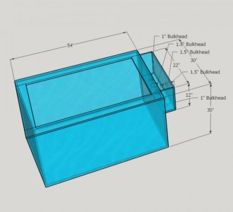
 

Attachments

  • p1.jpg
    p1.jpg
    37.7 KB · Views: 0
That's wonderful to hear. I just located a place with 1/2" glass at the same price as I can get 1/4" glass from most of the shops near my house, so I'm thinking of going 1/2" glass and running basically what you're running saf1. What size holes did you drill in the side of the tank? I really want to run an external overflow box with a lower profile internal overflow box, but I wasn't going to do it if I couldn't find properly sized glass, and people saying their external overflows were silent.
 
There are no holes on the side of the tank. Just the weir for the overflow - Outer holes, used for returns, are 1". Three inner holes are 1.5". I don't remember what the thickness of the overflow glass is but it is thinner than the overall tanks. The tank is 54" Wide x 30" Tall x 30" Deep.

Return 1" pipe in the picture above is just stubbed. Since then I've run one over the back of the tank along the Euro brace and plumbed in two 1" Sea Swirls. The return that is at the front of the tank is just turned off below and capped. I'll be adding another pair of Sea Swirls at a later date. It isn't needed at the moment since the tank is cycling.
 
saf1 they built it with the slot cut in the side of your tank, the "weir" is like a groove in the side panel? I don't really want to cut a groove in my tank, just do the pass-through holes. Also I think your overflow is well positioned at the side. My tank is 4 times longer than it is wide, so my overflow will be spanning the majority of the back panel.
 
The weir has you said should be smooth - or at least that is the general consensus here in the thread. It allows better skimming. Slots can plug up with debris, food, snails, etc. Mine is a bit hard to explain without a picture but in short it is an actual smooth weir. However, what they ended up doing, the tank builder, is glue a sheet of acrylic to that side of the tank, black, and at the top slotted it. It wasn't what I was expecting. What I expected is the sheet of acrylic with a weir but with a height of say 1/2" or so to act also like a fish guard. Instead they did that plus added slots. I've just not gone behind them to trim them off and smooth out so I have a basic weir. Go figure.

I'm not a fan of the slots because they can block and limit the effect the weir is supposed to accomplish. At least that is what I gathered form reading all of this thread.
 
Back
Top