You are using an out of date browser. It may not display this or other websites correctly.
You should upgrade or use an alternative browser.
You should upgrade or use an alternative browser.
Who wants a cheap, simple, Arduino-based LED controller?
- Thread starter der_wille_zur_macht
- Start date
Names Brucey
New member
I am working (again) on a revision of the hardware and would love to get some feedback before I proceed. I know I've asked several of these questions before but I never got a ton of feedback so please let me know what you think even if you're just lurking on the thread.
1) How important are more PWM outputs? Would it be worth adding a few components to get 6 output channels instead of 4?
2) How important is it to have BOTH 5v and 10v available on the end product? Would people be OK with one set of output headers? You'd make a decision while you built it to go either 5v or 10v and switching back and forth would entail getting the soldering iron out. Or, do people like the design as-is where there's a 5v and a 10v header for each channel, even if you're only typically using one or the other?
3) Is everyone else sick of the .1" pin headers currently used for the PWM outputs? I hate them.There aren't any easily-available sockets to plug on to them. I'm pretty set on switching to screw terminals, but this would mean a lot more area taken up on the board as screw terminals are inherently larger (and more expensive). Or maybe JST headers or something.
4) I've also gotten feedback that people don't like the fact that the buttons are not "on level" with the LCD, making it hard to put into an enclosure. Anyone have specific feedback on this, or can anyone confirm or deny this? A possible solution might involve soldering the LCD directly to the PCB instead of using pin headers to make it removable. Would that upset anyone?
Any other changes to the hardware that people would like to see?
1) Since I run 5 panels I would love 6 PWM outputs. Having only 4 is a pain for me.
2) I use only 5v pwm so that too would ideal.
3) Those pin headers are a pain. Screw terminals or another more readily available connection is more than welcome.
4) The buttons only really pose a problem for mounting the controller or putting it in an enclosure, which I would love to do. Soldering the LCD to PCB doesn't seem like a good idea to me because I have already experienced one LCD failure and trying to remove and remount one would seem like a huge pain. Mounting the LCD remotely is a good idea but I would love to keep it all together.
der_wille_zur_macht
Team RC
How about surface mount components, at least for super-easy things like resistors and capacitors? Would that be a turn-off for people?
I know many newcomers like through hole but IMHO surface mount is easier and faster once you get used to it. It also takes up way less space which means layout of the board is easier. I'd still leave hard stuff (the ICs) as through hole if people wanted...
I know many newcomers like through hole but IMHO surface mount is easier and faster once you get used to it. It also takes up way less space which means layout of the board is easier. I'd still leave hard stuff (the ICs) as through hole if people wanted...
Names Brucey
New member
No issue here with surface mount.
mm.reefs
Member
I am working (again) on a revision of the hardware and would love to get some feedback before I proceed. I know I've asked several of these questions before but I never got a ton of feedback so please let me know what you think even if you're just lurking on the thread.
...
Any other changes to the hardware that people would like to see?
Thinking on a more robust and versatile Typhon version (and not on my needs), here are my thoughts:
1) PWM Outputs: I would go with 6 PWM's, I dont see why to limit the Typhon on this. Just remember to include a jumper to select between one of the PWM pins or a 5v + resistor for LCD backlight control.
2)5v and 10v outputs: Yes, BOTH are important. Support for newer Mean Well drivers is very welcome!
3).1" pins: I'm ok with them. I love the idea of the screw terminals, but the resulting pcb size may be too big???
4) Buttons: Include .1" pins to use wired buttons. Push button remotely installed on the case are more practical.
Extras:
5)If possible, design the new Typhon pcb around a particular project box or pcb case, where it can be bolted directly without modifications and the LCD can be easily installed and seen from the outside.
6) Include .1" pins for Vin. This can be used to output 12v for an external pcb like the Hydra Relay board. (I think you already included this in the v1.0 pcb, not sure
 ???)
???)7)Surface mount components are nice to have, especially for saving space for the screw terminals.
^ +1
It does make more sense to have more PWM available, it's just not necessary for my current application, though it could be in the future.
IR does sound like a neat idea (and my wife already suggested the remote control RapidLED dimmer over the regular one), but I already have 4 remotes in my livingroom. 5 if you count the Wii. What remote would we use to control it? Or would that be another component to assemble?
I have never used SMT components, but I'm not afraid to try.
I definitely think wired buttons and project box intentions should be considered to make it more installation friendly, and more presentable. The wife asked what this controller was going to look like and how I was going to install it. So, I showed her some pictures and some ideas, and she decided that it needed to go in the stand so you couldn't see it, which was my reason for wanting to wire the buttons..
Last edited:
der_wille_zur_macht
Team RC
Just remember to include a jumper to select between one of the PWM pins or a 5v + resistor for LCD backlight control.
This is a big holdup to get the 6th channel. Freeing up one more pin to get 5 channels is easy, but I don't really want to give up the backlight control. As I'm sure you're all aware, in the current firmware, the backlight defaults to a dim setting when you're not interacting with it - dim enough to still view the numbers but pretty faint. Then when you're pushing buttons, it brightens up for easier viewing. If we used all 6 PWM pins for outputs, we'd lose the ability to switch between different brightness levels like this.
Not sure if that's a big deal to anyone or not.
2)5v and 10v outputs: Yes, BOTH are important. Support for newer Mean Well drivers is very welcome![/quote]
To be clear, I wouldn't permanently ditch one or the other. My idea is to have only ONE set of output headers, and you'd make a decision at build time to determine if a given output channel was 5v or 10v (i.e. solder a different resistor on or something like that). If you wanted to switch a channel you'd have to modify the hardware.
I'm considering this because I don't know of anyone (besides me) who is using some channels at 5v and others at 10v and needs to be able to swap easily. Having only one set of output headers would take up a LOT less space once we go to screw terminals or something else more robust than pin headers.
3).1" pins: I'm ok with them. I love the idea of the screw terminals, but the resulting pcb size may be too big???
See above.
It is going to be a struggle to make all these changes and keep the board size this small but I'm gonna try my best.4) Buttons: Include .1" pins to use wired buttons. Push button remotely installed on the case are more practical.
Extras:
5)If possible, design the new Typhon pcb around a particular project box or pcb case, where it can be bolted directly without modifications and the LCD can be easily installed and seen from the outside.
I have been on the fence about this for a long time. On the one hand, I love the current Typhon because it is "self contained" and doesn't require an enclosure to be "complete." If all we had were a row of pin headers to connect buttons to, you'd pretty much HAVE to put it in a box.
Ideally I'd design the new board so it can function "standalone" as with the current design, plus in a box. That's gonna be a challenge, though that's part of the fun.
6) Include .1" pins for Vin. This can be used to output 12v for an external pcb like the Hydra Relay board. (I think you already included this in the v1.0 pcb, not sure
Yup, 1.0 has pin headers for Vin. I'm powering mine from a bus powering lots of other devices so having the barrel jack is totally useless to me. I figured others might be in the same boat.
7)Surface mount components are nice to have, especially for saving space for the screw terminals.
Glad to hear not a single person arguing against surface mount (yet).
IR does sound like a neat idea (and my wife already suggested the remote control RapidLED dimmer over the regular one), but I already have 4 remotes in my livingroom. 5 if you count the Wii. What remote would we use to control it? Or would that be another component to assemble?
Check the Hydra thread, terahz just posted over there explaining how his IR functionality works. You basically put the controller into a learning mode, then point any IR remote at it and teach it what each button should do. If you had a multifunction remote with an unused function, you could just teach it to use that. Or buy a cheap $5 generic remote.
Unfortunately, Wii remotes won't work with this because they communicate over bluetooth, not IR (though they have IR receivers in them that pick up signals from the bar you put over the TV). I'd really love to link a Wii remote to a fish tank some day, though. Maybe version 3.
Thanks again everyone for the feedback and keep it coming. I'm working on the design right now but am still open to ideas.
Hello i'm working on a new version too, with the feedback of friends on the first version.
PWM: a few guys wants more than 6 channel (for fun 'left to right' sunrise, of for refugium, multiple colors), in my version the channel can be used pour moonlight, but with a lot of led on the channel 2-3% on the pwm is too much light
solution: PCA9685, 12 bits 16 channels.
4 channel reserved for servo")
5-10v: jumper to choose voltage, no direct pwm with arduino pin because some fried the arduino pwm.
Screw Terminal block connector for the vIn, more easy to use if the power supply is not connected to typhon, or on small tank to use same power supply for led & typhon
No LCD: bluetooth with pc/android interface, the lcd was hard to include, and the menu take too much memory: more space for weather or season variation of light.
buttons: has on my first version 1 wire deported buttons, but programmable (ex: button 1 to cycle all channel off, 1-2-3-4..., all off)
PWM: a few guys wants more than 6 channel (for fun 'left to right' sunrise, of for refugium, multiple colors), in my version the channel can be used pour moonlight, but with a lot of led on the channel 2-3% on the pwm is too much light
solution: PCA9685, 12 bits 16 channels.
4 channel reserved for servo
5-10v: jumper to choose voltage, no direct pwm with arduino pin because some fried the arduino pwm.
Screw Terminal block connector for the vIn, more easy to use if the power supply is not connected to typhon, or on small tank to use same power supply for led & typhon
No LCD: bluetooth with pc/android interface, the lcd was hard to include, and the menu take too much memory: more space for weather or season variation of light.
buttons: has on my first version 1 wire deported buttons, but programmable (ex: button 1 to cycle all channel off, 1-2-3-4..., all off)
Just remember to include a jumper to select between one of the PWM pins or a 5v + resistor for LCD backlight control.
I seem to remember reading earlier in the thread someone had freed-up the LCD dimming PWM, but still kept a dimming function by putting a push button switch inline for the backlight power. Push button to light it up, push button to return to dim. Brightness when on dim or bright mode could still be adjusted with a trim pot. Correct?
No LCD: bluetooth with pc/android interface, the lcd was hard to include, and the menu take too much memory: more space for weather or season variation of light.
This is also an idea I thought about, since I thought I had seen an Arduino Mega Android somewhere. Would be pretty cool to sit on the couch and control it with my Samsung GS2!

Edit: BTW, I'm still hoping someone has a left over v1.0 board I could aquire. Wanna get these lights going (without looking like a rats nest)! I could go and order the boards, but I'd rather not go that route just yet, especially if someone out there ordered 10 boards and only used 1 or 2.
Last edited:
firefightered66
New member
Could somebody please point me to the DIY for Dumbies Arduino led controller? I am getting ready to purchase my leds and drivers. All I want to do is dim them dusk-dawn. Nothing fancy or way over my head. I will need to know what and where to purchase everything I'll need for a simple set-up and then I'll need to know how to put everything together. As you can see there are more than a thousand posts in this thread and I'm not getting any younger. Thanks a bunch!
der_wille_zur_macht
Team RC
If you're referring to the Typhon, this is the thread for it.
The design files are here:
http://code.google.com/p/typhon-reef/
There's a schematic and board file in EAGLE format. You will need to download the EAGLE software and convert these to gerbers (search google if you don't know how to do that) and then send the gerbers to a board manufacturer (iteadstudio, seeedstudio, batchpcb, etc) to get the pcbs made. Here are those two files:
http://typhon-reef.googlecode.com/svn/trunk/hardware/typhon/typhon.brd
http://typhon-reef.googlecode.com/svn/trunk/hardware/typhon/typhon.sch
Then you will need to order the parts on the BOM (bill of materials) which is here:
http://typhon-reef.googlecode.com/svn/trunk/hardware/typhon/typhon_bom.xls
Then, solder it up.
Then, you will need to put the Arduino IDE on your PC, and get a way for the PC to talk to the controller. Typically this is with a USB-TTL converter from FTDI, like one of these:
http://www.sparkfun.com/products/9718
Then, get the Typhon firmware from the repo:
http://typhon-reef.googlecode.com/svn/trunk/software/typhon/typhon.pde
And upload it to the board.
der_wille_zur_macht
Team RC
Edit. Was going to ask another question but I think I'll just take a leap of faith and decide on my own.
firefightered66
New member
HOLY CRAP!!!!! I think this may be a little over my head.... Do you know of anyone who is willing to make me one? and how much$$$$
If you're referring to the Typhon, this is the thread for it.
The design files are here:
http://code.google.com/p/typhon-reef/
There's a schematic and board file in EAGLE format. You will need to download the EAGLE software and convert these to gerbers (search google if you don't know how to do that) and then send the gerbers to a board manufacturer (iteadstudio, seeedstudio, batchpcb, etc) to get the pcbs made. Here are those two files:
http://typhon-reef.googlecode.com/svn/trunk/hardware/typhon/typhon.brd
http://typhon-reef.googlecode.com/svn/trunk/hardware/typhon/typhon.sch
Then you will need to order the parts on the BOM (bill of materials) which is here:
http://typhon-reef.googlecode.com/svn/trunk/hardware/typhon/typhon_bom.xls
Then, solder it up.
Then, you will need to put the Arduino IDE on your PC, and get a way for the PC to talk to the controller. Typically this is with a USB-TTL converter from FTDI, like one of these:
http://www.sparkfun.com/products/9718
Then, get the Typhon firmware from the repo:
http://typhon-reef.googlecode.com/svn/trunk/software/typhon/typhon.pde
And upload it to the board.
der_wille_zur_macht
Team RC
To be clear, the point of this project is to get people to engage in DIY themselves, not to provide an off the shelf controller you can buy commercially. If that's what you're interested in, there are a handful of vendors that sell such controllers, and many reef controllers have optional modules that provide 10v analog outputs usable with many dimmable drivers.
Remember though, we all started where you are today at some point in our past.") It's definitely something an average handy reefkeeper can accomplish with a little time and effort.
It's definitely something an average handy reefkeeper can accomplish with a little time and effort.
Remember though, we all started where you are today at some point in our past.
It's definitely something an average handy reefkeeper can accomplish with a little time and effort.Pny
New member
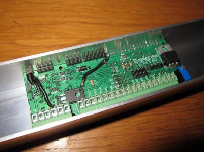
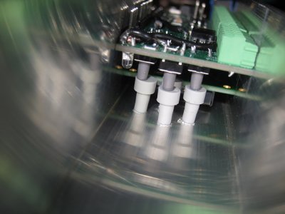
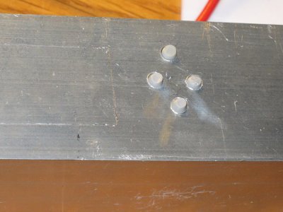
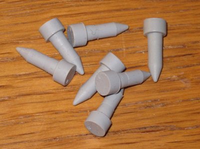
I don't use the Typhon (I've made my own Arduino Typhon-look-a-like) but I have about the same button design. For me, the problem with leveling the buttons was easy to fix, just adding some rubber extensions, see pics...4) I've also gotten feedback that people don't like the fact that the buttons are not "on level" with the LCD, making it hard to put into an enclosure. Anyone have specific feedback on this, or can anyone confirm or deny this? A possible solution might involve soldering the LCD directly to the PCB instead of using pin headers to make it removable. Would that upset anyone?
Attachments
firefightered66
New member
I would be willing to take this project on but I'm not sure where to get all the parts. Can most of this be purchased at your local Radio Shack?
To be clear, the point of this project is to get people to engage in DIY themselves, not to provide an off the shelf controller you can buy commercially. If that's what you're interested in, there are a handful of vendors that sell such controllers, and many reef controllers have optional modules that provide 10v analog outputs usable with many dimmable drivers.
Remember though, we all started where you are today at some point in our past.
sammy113
New member
I don't use the Typhon (I've made my own Arduino Typhon-look-a-like) but I have about the same button design. For me, the problem with leveling the buttons was easy to fix, just adding some rubber extensions, see pics...
Nice! what kind of rubber extensions are those? what are they used for or where to find them?
Here's what I came up with. Acrylic box with acrylic rod button extensions. In the inside has a wider piece just like those rubber extensions to keep them in place

Similar threads
- Replies
- 0
- Views
- 1K
- Replies
- 6
- Views
- 2K
- Replies
- 39
- Views
- 642
- Replies
- 23
- Views
- 3K