You are using an out of date browser. It may not display this or other websites correctly.
You should upgrade or use an alternative browser.
You should upgrade or use an alternative browser.
Who wants a cheap, simple, Arduino-based LED controller?
- Thread starter der_wille_zur_macht
- Start date
der_wille_zur_macht
Team RC
Yeah.
Though, we have to remember that all of this is highly subjective. Does it really matter if the dimming is totally linear? Our eyes aren't going to perceive a linear response as linear, anyways. And, the intensity of light on a natural reef does not change in a linear fashion. Even if you want totally linear dimming, it doesn't really matter if the driver's response curve is not linear, since we have total control over the signal being provided to the driver. Editing one or two lines of code in the core firmware could make the response shape look however you wanted it.
The one thing we really can't "fix" in software is the fact that both styles of ELN "cut off" low in the response curve.
TheFishMan65
New member
DWZM,
I think perhaps we are communicating poorly")
The dimming (as I recall) is not the same. There is no chart in the data sheet (did I miss is it) that states how a D will respond to a PWM signal. Where do you get 100 steps?Dimming performance would be the same as the digital version - i.e. you'd get a response as indicated in the datasheet, albeit chopped into 100 discrete steps.
I think perhaps we are communicating poorly
der_wille_zur_macht
Team RC
I think perhaps we are communicating poorly
+1.

What I meant when I said "the same as the digital version" was basically that it'll dim according to it's curve in the datasheet.
100 steps because the Typhon works on whole-number percentage increments, even though the AVR's PWM pin has higher resolution than that.
So, if you use the analog driver with a Typhon, it'll march up and down it's dimming response curve in 100 steps - just like the PWM version will march up and down it's own curve in 100 steps if used with a Typhon.
TheFishMan65
New member
Not enough knowledge of the Typhoon to remember it only has 100 steps - I need to get mine running
Yes they will both march up and down their curve, but IIRC the curves are very different.
Yes they will both march up and down their curve, but IIRC the curves are very different.
See the Hydra project I linked above - that's more or less our goal there. Build a "core" hardware and software library that let people construct a full-scale reef controller. Though it also has Ethernet hardware and a pH amp onboard, since it seems people who want a full-blown reef controller also want that stuff most or all of the time.
To reiterate, this project is *NOT* intended to be a full blown reef controller. It IS intended to control a few channels of LED drivers, and maybe some other stuff if you get creative (hence why I brought out an I2C header.) This definitely won't be all things to all people, and it probably won't be a very satisfying project for people who are well versed in this sort of thing and can do it themselves, because it'll seem overly simplistic. It's mainly intended for the people who have some basic tinkering/soldering experience but don't have a clue how to design and build a microcontroller - i.e. it's intended to make the entry point into the "microcontrollers for reef use" hobby a little more attainable.
Someone above picked up that I hinted at a $30 price point - to be clear, that's a very rough estimate based on parts cost. It'll be nice if it ends up being a cheap thing for people to build, but as someone else pointed out above, this isn't a cheap hobby, and price isn't the main driver here.
The design is made to plug in to the back of this display:
http://www.moderndevice.com/products/16x2-blue-lcd
There are tons of other 16x2 displays that are pin compatible, but I'm linking this one to help people visualize. The LCD will plug in to a pin header on the board, and the board has holes for standoffs that line up with the LCD's holes, so they can be screwed together. Basically, the bottom edge of the controller PCB will stick out below the LCD, and will have a row of buttons on it. The power jack and headers for programming (FTDI), I2C, and LED driver(s) will stick out the "sides" underneath the LCD.
I thought about modeling it in one of those 3d circuit rendering tools (i.e. fritzing) but I might as well just wait until the prototypes get here and I can build it for real.
So sorry but the thread is so long and it's late. But I see your still here so I was wondering if you ever built this ^ ^ ^ and if so can you PM details...
If cost is lower then -> http://www.ledgroupbuy.com/dim4-4-port-led-sunrise-sunset-controller-v1-0/ IDK if that would work? But seems like it would.. Using [2]Meanwell LPF-60D-48 drivers
Or my last option is Reef Angel
Thanks
See the Hydra project I linked above - that's more or less our goal there. Build a "core" hardware and software library that let people construct a full-scale reef controller. Though it also has Ethernet hardware and a pH amp onboard, since it seems people who want a full-blown reef controller also want that stuff most or all of the time.
To reiterate, this project is *NOT* intended to be a full blown reef controller. It IS intended to control a few channels of LED drivers, and maybe some other stuff if you get creative (hence why I brought out an I2C header.) This definitely won't be all things to all people, and it probably won't be a very satisfying project for people who are well versed in this sort of thing and can do it themselves, because it'll seem overly simplistic. It's mainly intended for the people who have some basic tinkering/soldering experience but don't have a clue how to design and build a microcontroller - i.e. it's intended to make the entry point into the "microcontrollers for reef use" hobby a little more attainable.
Someone above picked up that I hinted at a $30 price point - to be clear, that's a very rough estimate based on parts cost. It'll be nice if it ends up being a cheap thing for people to build, but as someone else pointed out above, this isn't a cheap hobby, and price isn't the main driver here.
The design is made to plug in to the back of this display:
http://www.moderndevice.com/products/16x2-blue-lcd
There are tons of other 16x2 displays that are pin compatible, but I'm linking this one to help people visualize. The LCD will plug in to a pin header on the board, and the board has holes for standoffs that line up with the LCD's holes, so they can be screwed together. Basically, the bottom edge of the controller PCB will stick out below the LCD, and will have a row of buttons on it. The power jack and headers for programming (FTDI), I2C, and LED driver(s) will stick out the "sides" underneath the LCD.
I thought about modeling it in one of those 3d circuit rendering tools (i.e. fritzing) but I might as well just wait until the prototypes get here and I can build it for real.
This is the whole idea of the project and yes it would be nice to have more features maybe as modules that can be bolted on later on
not understanding most of this thread but do fancy having a go
if anybody in the uk whats to help sourse the parts i am willing to have a go
der_wille_zur_macht
Team RC
So sorry but the thread is so long and it's late. But I see your still here so I was wondering if you ever built this ^ ^ ^ and if so can you PM details...
I did build it and at least 120 other people have, on my count. That's what the thread is about. Read through and ask if you have questions. The post you quoted is essentially accurate - cost depends on where you buy parts, what you already have on hand, and so on - but it will almost always be cheaper than any commercial product.
I am in progress with a redesign, but it will likely be a few months, so if you want something quick, the current version might make sense.
shark boy
New member
If more pwm channels were added wouldn't the interface have to change to something like an I2C input for the screen?
That would effect the layers of the board or the size of the pcb, also if the screen size increased to say a 20x4 the footprint on that is a lot larger as well.
Seems like either way the new Typhon will not look like the old Typhon.
I can't wait to see the new design.
shark boy
That would effect the layers of the board or the size of the pcb, also if the screen size increased to say a 20x4 the footprint on that is a lot larger as well.
Seems like either way the new Typhon will not look like the old Typhon.
I can't wait to see the new design.
shark boy
der_wille_zur_macht
Team RC
Seems like either way the new Typhon will not look like the old Typhon.
This is true. It won't be the same size and the interface will be improved overall. It will still fit in the 10x10 category so the cost for the board (from places like iteadstudio) will not increase. Cost overall will probably be up about $10 but I'm pretty confident it's justified.
trodrigues
New member
does anyone have any extra typhoon boards, I am looking for 1 bare board
Question.
What exactly does this version / thread allow to be controlled? I'm a bit confused now since I think I'm following two or more different build threads :hmm4:
I keep thinking this one is the LED dimmer and controller (on/off), temp probe option, ph option, and network? Or...was it just to control LEDs.
The hydra is what I'm thinking but there are so many pages I'm not sure where 'go' or 'start here' is anymore. Now it looks like another build thread is separating PH? Right now our LED's come on and off for x amount of time. I think corals and the one retro kit's power supply would be happier if it was on at x time, then slowly increased, all on, then slowly decrease, until off. Temp and network would be ideal, as a option for turnning on/off stuff but I'm not one to be able to take a basic design and add.
I need to follow a recipe sadly
GREAT job to everyone who has helped move the Typhoon forward to where it is today!
I've been following this thread as well as the Hydra for quite some time. I've device to build the Typhoon sooner than later simply because I'm getting a little tired of paying $400 bi-monthly for electricity. I've even thought of shutting down the tank to same on my monthly expenses since both my kids have lost interest in the aquarium..........a side effect of Finding Nemo!
I've downloaded the necessary files from the google code site.
Installed Eagle on my laptop.
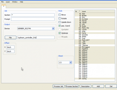
Thank to DWZM, I'm following his Eagle instructions to get the Gerber files created for the BCB house. When I run the cam by clicking on the build film icon, I get the following which is very different from what DWZM posted in thread #264.
I've attached a screen shot of what I saw when I selected the CAM button. Is this correct? If not, what am I doing incorrectly?
I entered TYPHOON_CONTROLLER as the output file. I see 2 files created after I clicked on PROCESS JOB
1] typhoon_controller_pcb (no extension)
2] typhoon_controller_pcb.gpi
Are those the only 2 files created which needs to be sent to a PCB house like iTead Studio?
How do I verify the Gerber files are correct?
Thanks in advance to any advise.
Thank you!!
I've been following this thread as well as the Hydra for quite some time. I've device to build the Typhoon sooner than later simply because I'm getting a little tired of paying $400 bi-monthly for electricity. I've even thought of shutting down the tank to same on my monthly expenses since both my kids have lost interest in the aquarium..........a side effect of Finding Nemo!
I've downloaded the necessary files from the google code site.
Installed Eagle on my laptop.
Thank to DWZM, I'm following his Eagle instructions to get the Gerber files created for the BCB house. When I run the cam by clicking on the build film icon, I get the following which is very different from what DWZM posted in thread #264.
I've attached a screen shot of what I saw when I selected the CAM button. Is this correct? If not, what am I doing incorrectly?
I entered TYPHOON_CONTROLLER as the output file. I see 2 files created after I clicked on PROCESS JOB
1] typhoon_controller_pcb (no extension)
2] typhoon_controller_pcb.gpi
Are those the only 2 files created which needs to be sent to a PCB house like iTead Studio?
How do I verify the Gerber files are correct?
Thanks in advance to any advise.
Thank you!!
Attachments
Jay1982
New member
The design files are here:
http://code.google.com/p/typhon-reef/
There's a schematic and board file in EAGLE format. You will need to download the EAGLE software and convert these to gerbers (search google if you don't know how to do that) and then send the gerbers to a board manufacturer (iteadstudio, seeedstudio, batchpcb, etc) to get the pcbs made. Here are those two files:
http://typhon-reef.googlecode.com/svn/trunk/hardware/typhon/typhon.brd
http://typhon-reef.googlecode.com/svn/trunk/hardware/typhon/typhon.sch
Then you will need to order the parts on the BOM (bill of materials) which is here:
http://typhon-reef.googlecode.com/svn/trunk/hardware/typhon/typhon_bom.xls
Then, solder it up.
Then, you will need to put the Arduino IDE on your PC, and get a way for the PC to talk to the controller. Typically this is with a USB-TTL converter from FTDI, like one of these:
http://www.sparkfun.com/products/9718
Then, get the Typhon firmware from the repo:
http://typhon-reef.googlecode.com/svn/trunk/software/typhon/typhon.pde
And upload it to the board.
Anyways, this post here was pretty useful but I still have a lot of gaping holes for me to fill. 99% of the jargon in this thread is Chinese to me so forgive me for my basic questions.
I`m in waaaaaaay over my head but I`m in desperate need of a controller. So I will try and do this myself despite having 0 experience. Originally I had someone who was ready to help me out but I think he`s either backed out or gotten fed up with my constant questions, lol.
I guess the important thing to ask is, if I screw up is there the potential for burning out or blowing my drivers or LEDs? If so I will need to find someone to build me one because I can`t lose the odd thousand dollars I sunk into my array.
My setup is 9 meanwell ELN 60 48ps; currently they are run with analog devices but my schedule leads me to not being around my aquarium when the lights need to be turned off and on. What I am looking for in this controller is one that can turn on and off the LEDs throughout the day as well as have extra programs like storms and cloud cover.
Anyways, now that that is out of the way, here are my main questions regarding the build process:
Can this unit be constructed in a day or should I plan a few days worth of time to making this?
The BOM file is my holy grail at this point because I have no idea what these parts are or look like. My main problem though is that some parts don`t have a part number to it; if I go on mouser and input the device or value name I get either 0 hits or a thousand. Is this because the list I am using is old?
Another issue I am having is when I go to http://code.google.com/p/typhon-reef/ for design files I am getting a empty pages. Also, I see I will have to download eagle to get the schematics to wire the device; I did a search for eagle software and have quite a few hits. Is this freeware or is there a specific company that has the software?
I would need at least 5 10v channels since I am running 9 drivers, what do I need to do differently to achieve this?
In terms of loading sketch I see I will need to put the Arduino IDE on my PC, and get a way for the PC to talk to the controller. Typically this is with a USB-TTL converter from FTDI; however I have noticed that this is a wire; is there a wireless way of doing this? My computer is no where close to where my controller will be.
Finally, my last question (for now :fun5
is that someone mentioned a wiring diagram for the drivers controller and LEDs; I can`t find it for the life of me on this thread. Does someone have one I could borrow; I`ll give it back, promise.Thanks to anyone still reading, lol :thumbsup:
Jay1982
New member
I no longer need help resolving the problem of having the google page come up blank.
If someone can look at the picture below just tell me if this is right for wiring the final unit to the LEDs. I see from reading the thread that I can only have 2 drivers per channel; hook up the blues with the blues, blacks with the blacks. My confusion is where do the red wires lead to? I assume its the LEDs; do I wire the beginning and end of the series of LEDs with the red wire from the meanwell?

If someone can look at the picture below just tell me if this is right for wiring the final unit to the LEDs. I see from reading the thread that I can only have 2 drivers per channel; hook up the blues with the blues, blacks with the blacks. My confusion is where do the red wires lead to? I assume its the LEDs; do I wire the beginning and end of the series of LEDs with the red wire from the meanwell?
hey all! I just wanted to say that I have also built the typhon using an arduino mega 2560 and i have been super impressed !!
I have made added a few things to try to push its abilities a little further and so far I have working:
*using 20x4 lcd instead of 16x2
*set 1 channel to be moonlight by making it inverted and then modifying
the analogwrite map to match the non inverted map except make the
minimum value of this channel as the maximum value of the
moonlight(used a string of only RB cree 3w XT-E).
*using dallas temperature probes, 3x and displaying them on the screen
beneath the 4 channel values (extra room in lcd thanks to 20x4 size).
still working on:
*adding 5th channel to act only at dawn and dusk...hoping to have a few
orange/yellow led's simulate sunrise and sunset beyond just typical
white/blue spectrum
*extra menu to choose which string is the moonlight (switch the boolean
value to true or false through the menu)
*ethernet connection for both display of temp and light settings as well as
ability to adjust led channels using android smartphone
* use relay board to make wavemaker with arduino (thinking of using a
simple blink program and modifying the delay between blinks to be appropriate for wavemaking
*use a magnetic relay (typically used in security systems on doors or windows) on sump cabinet doors that can trigger a worklight for
extra lighting beneath the tank
just a few fun ideas to see what can be done using this platform........I'm quite new to the whole scene and so far have enjoyed the heck out of messing with arduino language and getting this thing put together from scratch.
I hope there are others out there tinkering with this as well still.
thanks all!
Last edited:
hey all! I just wanted to say that I have also built the typhon using an arduino mega 2560 and i have been super impressed !!
I have made added a few things to try to push its abilities a little further and so far I have working:
*using 20x4 lcd instead of 16x2
*set 1 channel to be moonlight by making it inverted and then modifying
the analogwrite map to match the non inverted map except make the
minimum value of this channel as the maximum value of the
moonlight(used a string of only RB cree 3w XT-E).
*using dallas temperature probes, 3x and displaying them on the screen
beneath the 4 channel values (extra room in lcd thanks to 20x4 size).
still working on:
*adding 5th channel to act only at dawn and dusk...hoping to have a few
orange/yellow led's simulate sunrise and sunset beyond just typical
white/blue spectrum
*extra menu to choose which string is the moonlight (switch the boolean
value to true or false through the menu)
*ethernet connection for both display of temp and light settings as well as
ability to adjust led channels using android smartphone
* use relay board to make wavemaker with arduino (thinking of using a
simple blink program and modifying the delay between blinks to be appropriate for wavemaking
*use a magnetic relay (typically used in security systems on doors or windows) on sump cabinet doors that can trigger a worklight for
extra lighting beneath the tank
just a few fun ideas to see what can be done using this platform........I'm quite new to the whole scene and so far have enjoyed the heck out of messing with arduino language and getting this thing put together from scratch.
I hope there are others out there tinkering with this as well still.
thanks all!
Sounds Cool, I'd like to see more details on that when you get it done. I'm still building SMD versions of the original typhon, so I'm a bit behind in adding extra functionality.
Similar threads
- Replies
- 0
- Views
- 1K
- Replies
- 6
- Views
- 2K
- Replies
- 39
- Views
- 715
- Replies
- 23
- Views
- 3K