DIY LEDs with Radion Pro G2 pucks?

DIY LEDs with Radion Pro G2 pucks?

I tried researching it last night the package number is B2TK, couldn't find any information online on it...

I am pretty much debating if I should go with 4 or 5 18" maker led they are pretty pricy but includes a fan splash gaurd and they are completely closed so dust doesn't get on the LEDs... Hopefully will last longer that way.

I wonder if I am over killing it a little, planning to light up a 265 gallon tank 84by30 inches two pucks on each heat sink

Here's a picture from me playing around with it yesterday...
aru2y9ed.jpg
 
nice pics. Which pucks are those? Gen2 pros? How many pucks are you running over that sized tank?

I'd assume the maker's would work and make a nice looking solution. I don't like that the channels (for the screws) would leave gaps where the puck is not touching the heatsink, though... MAYBE this is no big deal due to the aluminum PCB.. but I don't have enough experience to say one way or the other.

If it is a problem, maybe you could use extra pieces of aluminum to attach each of the pucks to?

I'd planned to make a cover for the bottom of my fixtures, that'll hide all the wiring, with holes for the optics to shine through.

So, your temp sensor (if that's what it is) is labled B2TK? Interesting... definitely a different number than mine.
 
Those are the G3, didn't think the pros were worth the extra 100$.

i currently have no lights over the tank... still building everything out. But was thinking to hang 5 fixtures with regular TIR lenses.

I created one fixture with 2 Lumia 5.2 for my frag tank, the lumias are around 70 Watts, where based on my calculation if you run the G3 puck at full intensity it would be around 65Watt for each. I don't have any heat issues with the lumias and I ended up drilling 4 holes to pass the wires to the back. The good thing about those grooves is that you could pass the wires through them, and use some kepton tape to secure them in place.

I plan to run the first 2 + 4 at 1000ma (instead of 1500), and the rest on 700.
 
Interesting read - caught up over coffee this morning. So is the general thought now to go this route rather than driver, power supply, heat sink, and your own design? Seems we have evolved over time since I last built my own LED solution.

I'm planning a 100 to 300 gallon tank and playing catch up with the LED crazy :) I currently have two 29 gallon bio-cubes one that uses Steve's retro kit and the other using the one from Rapid LED. So I've been toying with the quad drivers from Steve's and some Phillip's LED's since I can dim to 0 with my reef angel controller.

Wanted to say thanks for the thread, some great information here.

Not sure I follow your first paragraph completely... These pucks are simply a way of getting a compact array of LEDs for a debatably reasonable price. We are still using heatsinks, power supplies, and drivers just like any other DIY build. And, you could still customize your design and spectral range by adding any additional LEDs you want.
 
Oh now I hadn't considered that some of the extra pins on the Puck could be temperature monitoring. That's possible.

On a Gen1 Puck the connections are

Pin1 - White +
Pin2 - Royal Blue +
Pin3 - Blue +
Pin4 - Red+
Pin5 - Green +
Pin6 - Royal Blue -
Pin7 - Blue -
Pin8 - White -
Pin9 - Green -
Pin10 - Red -

Then pins 11-14 must be puck ID ( to determine which pucks are fitted to the board ) and possibly temperature monitoring.

In the UK we can buy the pucks to do the upgrades ourselves so access to the old pucks isn't too bad. Sadly everyone is upgrading Gen1 to Gen3 right now so they are the only pucks readily available so my information is only available for Gen1.

Interestingly the white, red, green, and blue are linked in the loom from the pucks to the main control board, so they are each made into a single string of each colour. The Royal blue however has two strings of 5 connected to the main board and they run on separate channels on the main board.

Assume this pin out is perfect, Anyone figure out the rest of the pin out from pin11 to pin 16 of this connector of the G2/Pro/G3/G3Pro?. If anyone upgrade themself, what is the spec for the fuse?
 
Wanted to post a pictures of the pucks on a heat sink :) going to order a Ldd 6 up tomorrow so I could hoke it up permanently

uzujuvas.jpg


yqaparus.jpg
 
Assume this pin out is perfect, Anyone figure out the rest of the pin out from pin11 to pin 16 of this connector of the G2/Pro/G3/G3Pro?. If anyone upgrade themself, what is the spec for the fuse?

That is gen1 puck pin-out. There was a gen2 (and probably gen3) pin out listed as well shortly after that one. No one has posted 13-16 yet.
 
Temperature and puck detect probably. Definitely pick detect as the main board is the same for Gen1, Pro, gen2. It's just the Sw detects which pucks are there.
 
Temperature and puck detect probably. Definitely pick detect as the main board is the same for Gen1, Pro, gen2. It's just the Sw detects which pucks are there.

hmmm... this drawing changes a bit (specifically the 'ground' pin) if that is a transistor and not a temp sensor. lol. I wasn't able to determine anything yet for sure using my multimeter and 5V wall wart.
 
I couldn't figure out what the circuit was either. I'm just guessing it has to be puck ID and temp as the radion does check for temperature and it has to be in the pucks as the main board isn't bonded to the heat sink.
 
There's a possibility that we're not able to test sufficiently with a multimeter because the temp signal is digital. I've not messed with a digital temp sensor before, but will try to pull my controller offline to play with it some more this week/weekend. If it is digital, it might be good. I think we'd be able to tie the signal wires together and bring them to the controller via 1 single wire (that will also hold up to distances much better than an analog signal wire).

If anyone with has any ideas or suggestions, please share... :)
 
Last edited:
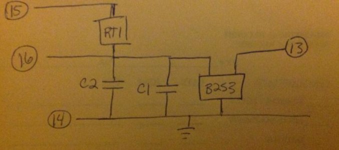
I think this is the circuitry for pins 13-16. Not totally sure what all four pins are for...
attachment.php

Looking at this I'm going to go out limb here:

13 = Board ID (possibly determined by the value of C1 and C2 though I could be way off here)
14 = Ground
15 = Temp read out from thermistor (resistance across it translates into temp)
16 = Power
 
Last edited:
This meanwell CLG-15036A will enough to drive 2 Gen1 or 2 Gen2 puck and super cheap only $13 shipped. regular is $70.


http://www.ebay.com/itm/MEANWELL-CL...673?pt=LH_DefaultDomain_0&hash=item2a3afdbbe9

Ohh cool thanks for the link, I wonder why these are so heavily discounted. Is there any difference in these sealed PSU versus the bulkier swiss cheese enclosure style ones mentioned previously?

Looking at the datasheet it looks like the A version has an internal potentiometer for adjusting the current/voltage. For this application would you just leave it at 36V 4.2A, aka full blast?
 
Back
Top