DIY LEDs with Radion Pro G2 pucks?

Ohh cool thanks for the link, I wonder why these are so heavily discounted. Is there any difference in these sealed PSU versus the bulkier swiss cheese enclosure style ones mentioned previously?

Looking at the datasheet it looks like the A version has an internal potentiometer for adjusting the current/voltage. For this application would you just leave it at 36V 4.2A, aka full blast?

These are nearly water proof and are way better quality, assuming they are legit. Vendor has good ratings and looks to be a wholesale clearing house type of place selling off old new stock items in bulk so I'd suspect they are the real deal.

Get them while they are HOT!!!!!!! Just bought enough for all my upcoming and future LED projects...........going fast.....

Sweet thanks for the confirmation! I tried to compare it with a bunch of other 150W enclosed fanless Meanwell PSUs but couldn't see the differences. I couldn't even find what "category" of AC-DC PSU these fall under on Powergate. I'll be picking up a few for sure then :cool:
 
Sweet thanks for the confirmation! I tried to compare it with a bunch of other 150W enclosed fanless Meanwell PSUs but couldn't see the differences. I couldn't even find what "category" of AC-DC PSU these fall under on Powergate. I'll be picking up a few for sure then :cool:

They are constant current or can be used as constant voltage power supplies since they are the A type you can adjust them both voltage and current limiting.

You can use them to power LDD drivers or you could wire several strings of pucks in parallel and use them as the driver directly (though would not be dimmable in that case, only on/off)

Even more good info, thanks! So one of these can drive a pair in series with 5 LDD-700?
 
This meanwell CLG-15036A will enough to drive 2 Gen1 or 2 Gen2 puck and super cheap only $13 shipped. regular is $70.


http://www.ebay.com/itm/MEANWELL-CL...673?pt=LH_DefaultDomain_0&hash=item2a3afdbbe9

Good find! Thanks.


They are constant current or can be used as constant voltage power supplies since they are the A type you can adjust them both voltage and current limiting.

You can use them to power LDD drivers or you could wire several strings of pucks in parallel and use them as the driver directly (though would not be dimmable in that case, only on/off)

What exactly can you adjust with these? You are saying you can make them work as constant voltage PS OR constant current driver ? I've never used one.

Could you use potentiometers to dim the parallel circuits? How does dimming LEDs using Pots work - you varrying voltage and not current, right? That's why you can't dim to 0 - because LEDs have a minimum operating voltage?

There are two little potentiometers inside the case, accessible thru two holes in the case with removable rubber plugs. One pot adjusts the current limiting circuit + or - the output amps within the drivers range. The other pot adjust the maximum output voltage + or - within the driver's range. For use as an LED driver directly minimum current is like 2.1 amps or something within a voltage range of 27 to 40-ish volts on the LED string. LED driving you just turn the voltage pot all the way up and the driver adjust voltage below that based on the LED strings need at whatever output current you set.

To use it as a voltage supply driving LDDs or such you simply max out the current setting and then adjust the voltage pot to suit your setup in that mode it only supplies whatever current is drawn by the devices connected to it, the LDDs do the current limiting just like a normal PSU.

You cannot use pots to adjust a parrelel array with this driver. there is no dimming capability, they all come on and all turn off when the driver is powered on or off.

For LED dimming to zero you must use the LDD drivers with this power supply.

For the general purposes of this thread you will be using LDDs and just treat the CLG as a normal old power supply (just better quality)

:reading: :thumbsup:
 
progress

progress

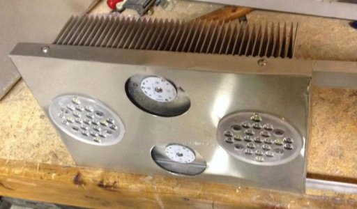
My drivers should ship this week! Excited about that. I've also been making progress on my build. I have wiring harnesses made up and my structure and covers are built. Here's a pic of one of the completed covers - the white 4-ups will hold two more violets each, and two cyans each. They won't have optics and I'm running wide angle optics on the radium pucks.

It's starting to come together... Although one big step left will be to reflow solder the extra LEDs to 4-ups and the pucks. :worried:

I'm excited to get some power on these guys, though!

cover.jpg
 
My drivers should ship this week! Excited about that. I've also been making progress on my build. I have wiring harnesses made up and my structure and covers are built. Here's a pic of one of the completed covers - the white 4-ups will hold two more violets each, and two cyans each. They won't have optics and I'm running wide angle optics on the radium pucks.

It's starting to come together... Although one big step left will be to reflow solder the extra LEDs to 4-ups and the pucks. :worried:

I'm excited to get some power on these guys, though!

Looks awesome! Those fins are gigantic, guessing you probably don't need a fan for cooling. Do you have any sort of non-conductive panel for all your electronics within to avoid any shorting etc? I'm planning to do something similar but with wood/acrylic instead. Do you have any shots of the wiring harness you made? Did you use two of the 14 pin JST connectors mentioned previously to connect the pucks together then to your controller?

check out this heat sink kit. To me it awesome, come with safety feature like protection guard, screw hole, mounting ...... you can get this for difference length if you have a long tank.

http://www.ledsupply.com/led-heatsinks/makersled-heatsink-kit?gclid=CMDppqam470CFVKDfgodvbgAUw

LED GB has been marketing these MakersLED heatsink kits for a while now. My old 6" full spectrum fixture was a 6" kit from them. It's a very simple, clean and easy way to build an LED fixture but doesn't leave much room for customization. I'm planning my build to have everything enclosed in my light fixture including PSU, LDD-5 board and controller with one power cord to the PSU running to the fixture
 
Last edited:
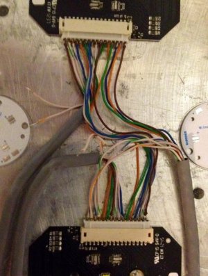
I'm using the 16 pin connectors on gen2 pucks. Cat 6 cables. 1 carries all positive DC signals, 1 carries all negative DC signals, and one attaches to pins 13-16 on both pucks for carrying temperature circuit wiring (yet to be figured out).

image.jpg
 
I'm using the 16 pin connectors on gen2 pucks. Cat 6 cables. 1 carries all positive DC signals, 1 carries all negative DC signals, and one attaches to pins 13-16 on both pucks for carrying temperature circuit wiring (yet to be figured out).

Cool thanks for the info and picture...any reason you didn't just make wire the two pucks togther like Driver (+) -> P1 (+) -> P1 (-) -> P2 (+) -> P1 (-) -> Driver (-) ? Then you could essentially have just one cord going from your pucks to your drivers.
 
Cool thanks for the info and picture...any reason you didn't just make wire the two pucks togther like Driver (+) -> P1 (+) -> P1 (-) -> P2 (+) -> P1 (-) -> Driver (-) ? Then you could essentially have just one cord going from your pucks to your drivers.

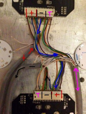
The pucks are in series and I will drive each color separately for complete color control. I have at least one driver for each color. The extra non-covered wires in the picture between the two pucks are what connect the two pucks into series and I believe what you are also explaining. On Gen 2, there are 6 color circuits. 6 + leads, and 6 - leads, then 4 extra for the temperature and whatever else.

Each Cat6 cable has 8 conductors. I also have the addition of the 4-ups that will hold cyans and violets. So, 6 conductors from the first cable go to puck 1 DC positive pins (one that doesn't go to the puck will go to the 4-ups and one will be unused). 6 more conductors go from puck 1 negative connectors down to positive pins on puck 2. Then the 6 negative conductors come off puck two through the second Cat6 cable and back to the driver boards. The negative from the 4-ups will also come back through this conductor - again leaving one unused conductor in that cable. The third cat6 cable will carry the 4 extra pins for both pucks together.

Does that make sense? I think that is what you are explaining already..

wireHarnes2.jpg
 
Last edited:
Ohh okay, thanks for the clarification, ya that is pretty much exactly what I was thinking but I was trying to think of a way to combine all the LED +/- wires into one main loom for both pucks like the OEM Ecotech harness. But in that case you'd need a 32 conductor cable. Would be nice to just be able to buy the OEM Ecotech harness all complete like this:

attachment.php


Don't the Radion Gen 2 non-pro pucks have 5 LED color channels not 6? Did you wire in the extra red/violet channels for future expansion or was there another reason for this?

Unless I'm missing something here, if I don't incorporate the 1 extra color channel (non-pro) as well as the 4 extra temperature/etc ones I would need only one single 10 wire conductor cable to wire up both pucks in series, with wires running between the two of course.

Driver (+) Cable Conductor 1 -> P1 CW (+) -> P1 CW (-) -> P2 CW (+) -> P2 CW (-) -> Cable Conductor 2 -> Driver (-)

No wires between P# (+) -> P# (-) just shown for clarity, then repeated for the remaining channels: RB, B, Gr, R
 
DIY LEDs with Radion Pro G2 pucks?

I can only say for certain on the gen1 pucks ( as in my photo you've used ) but yes there are 5 channels of colours but 6 channels to the radion pcb. The royal blues are split into a channel per puck, the other colours are linked between pucks to run them in series.

But yes you are correct, you only need 10 wires going to the drivers and then run 5 wires between pucks to run them if you're running off your own drivers.
 
Ohh okay, thanks for the clarification, ya that is pretty much exactly what I was thinking but I was trying to think of a way to combine all the LED +/- wires into one main loom for both pucks like the OEM Ecotech harness. But in that case you'd need a 32 conductor cable. Would be nice to just be able to buy the OEM Ecotech harness all complete like this:

Don't the Radion Gen 2 non-pro pucks have 5 LED color channels not 6? Did you wire in the extra red/violet channels for future expansion or was there another reason for this?

Unless I'm missing something here, if I don't incorporate the 1 extra color channel (non-pro) as well as the 4 extra temperature/etc ones I would need only one single 10 wire conductor cable to wire up both pucks in series, with wires running between the two of course.

Driver (+) Cable Conductor 1 -> P1 CW (+) -> P1 CW (-) -> P2 CW (+) -> P2 CW (-) -> Cable Conductor 2 -> Driver (-)

No wires between P# (+) -> P# (-) just shown for clarity, then repeated for the remaining channels: RB, B, Gr, R

I can only say for certain on the gen1 pucks ( as in my photo you've used ) but yes there are 5 channels of colours but 6 channels to the radion pcb. The royal blues are split into a channel per puck, the other colours are linked between pucks to run them in series.

But yes you are correct, you only need 10 wires going to the drivers and then run 5 wires between pucks to run them if you're running off your own drivers.

Ya, I think you're both right. The Gen2 pucks have a 6th color channel (for violets) that is not used unless they are pro version. I wouldn't be surprised if the Gen2, Gen2 pro, and Gen3 pucks were all the same PCB, as all the same spots exist for LEDs in the same places. The only differences MIGHT be the size of the mounting sockets for different model LEDs.

I accuired some UV LEDs to add to that 6th channel, and a lower spectrum red-orange to add to the center open spot (adding to the red) channel. So I intend to fill in the unused spots on my pucks. The lower spectrum reds are to counter the Cyan on the 4-ups, and more UV to add more 'pop' to the 4-ups as well. So, should hopefully fill in color spectrum well. I didn't come up with this plan completely on my own - lots of questions to others, including Zachts, O2Surplus, and kaserpick concerning color selections and soldering feasability.

My big hurdle now is the reflow soldering.
 
Ohh okay, thanks for the clarification, ya that is pretty much exactly what I was thinking but I was trying to think of a way to combine all the LED +/- wires into one main loom for both pucks like the OEM Ecotech harness. But in that case you'd need a 32 conductor cable. Would be nice to just be able to buy the OEM Ecotech harness all complete like this:

attachment.php


Don't the Radion Gen 2 non-pro pucks have 5 LED color channels not 6? Did you wire in the extra red/violet channels for future expansion or was there another reason for this?

Unless I'm missing something here, if I don't incorporate the 1 extra color channel (non-pro) as well as the 4 extra temperature/etc ones I would need only one single 10 wire conductor cable to wire up both pucks in series, with wires running between the two of course.

Driver (+) Cable Conductor 1 -> P1 CW (+) -> P1 CW (-) -> P2 CW (+) -> P2 CW (-) -> Cable Conductor 2 -> Driver (-)

No wires between P# (+) -> P# (-) just shown for clarity, then repeated for the remaining channels: RB, B, Gr, R

Btw, I think you could make something almost as pretty with individual wires and wire shrink tubing... Notice that's all they've used: that mesh tubing with shrink tube on each end. That mesh stuff probably works like Chinese finger cuffs, you can push it together and expand your opening to get your wires through, and then seal it with the shrink tubing.
 
Just finished my simple build. 1 set of spare radion gen1 clusters. 1 x 40w 24v ac to dc led driver powering whites and blues. DONE (sump only)
 
I just got my Radion Gen 2 pucks in yesterday :dance: I have the PSU/fan on the way as well. Still need to order the rest of my components but I've been looking at 10 conductor cables on Digikey since I have to get my connector and terminals there anyways but it looks like they're non-stock items so high minimum order and price ~$1/foot but 100 ft minimums for most which is way more than I need. I think I'll end up using two separate cables like you shorty but bundle them together or make my own loom.

Just finished my simple build. 1 set of spare radion gen1 clusters. 1 x 40w 24v ac to dc led driver powering whites and blues. DONE (sump only)

Any pictures of your build?
 
Back
Top