Silent and Failsafe Overflow System

First off: cut the pipes off, so that the outlets are less than 1" below the water level in the sump. (basic setup instructions)

The siphon capacity of a 1" line is right around 2000 gph w/36" drop, which is right where this tank should be running. So, I think you should be running a larger siphon--rather than pushing the limits of your siphon line.

On your return pump performance: You have made some errors in the setup. First you are running the pump output right into a brick wall with the Tee attached to the back of the stand, and you have reduced the pipe diameter to 1" going up into the tank, and over into the sump it looks like. That is why you can't get any flow out of it. Too much friction loss, w/too many fittings and direction changes as well as too small a pipe diameter.

45 off of the pump outlet, over a bit, then 45 up to the tank, better would be to go straight up from the pump, eliminating the 45's in the upward run) and run the return up over the back of the tank. (yes I know you have a hole drilled, unfortunately it is too small for this pump) Tee off the line over to the sump. Keep the pipe size 1.5" entirely. Do not reduce it. For better performance increase the pipe size to 2".

Another problem with your pump plumbing is the 90° elbow right at the pump inlet. Sweep or not, this will cause a differential pressure (difference in velocity of the water entering the pump, between the inside of the curve and the outside of the curve) in the pump volute, that will cause the pump to cavitate. You need a straight run to the pump inlet ~ 7 - 10 times the pipe diameter.

Just an idle comment, I would not have wasted the money on a dart gold pump, rather a standard dart for this tank.

If my plans where to stay with just the DT and Fuge running off of the main pump I would have plumbed it as you suggest, however, I chose a manifold design for the main pump system because in the future I will add several other tanks (frag, and (2) more in wall DT's). My design was to utilize one pump instead of running several. The mistake I made was not sizing the pump with Reef-flo before ordering it. I talked with them today and they are going to "get my back" by replacing my Dart with a Hammerhead/Barrracuda Hybred, at no additional cost except shipping, It will be capable of creating higher pressure to move the amount of water necessary. All of your plumbing mods. recomendations I understand, however, Chriss at Reef-flo did not feel the sweep 90 at the inlet was a problem. The real world resides in my fish room and does not allow best case senario in all applications. Thanks for your in-put, do you have any suggestions on how to improve flow between sumps and sump and "fuge"? I'm not sure whether a larger diameter connection or just another 2" connection would be best...............Budster
 
Thanks for the responses uncle and dwolson. I hate to bother the thread with stupid questions, but here's a couple more :) Hope I don't insult anyone's intellect here.

I'm thinking about just doing a spigot elbow straight out of the tees to save that 1/2" of space, lol. Is there an advantage to having a longer distance between the elbow's intake and the weir inside the tee? I may be overthinking this, just wondering if there's a rule I'm breaking by limiting that distance and having the extra reduction that a spigot elbow would create.

Also, these would all need to be slip. Any discernable issue not gluing the submerged areas (ie, base of the tee - so the whole tee can pop off if needed) as it relates to the siphon? If I glue them entirely I don't think I'll have room to unscrew them from the bulkhead which is threaded.

I have used a threaded t before then a threaded elbow. You can get a threaded nipple to connect to the bulkhead. That will take less space. If you want it to be easier to clean, why not use a threaded plug? I have used them in the past. I currently use a threaded cap, because I used a slip t this time, and had to convert it to threads before i could cap it. I would think that just sliding on a cap would work, or any pieces for that matter, but I like it glued if possible. Then I know I won't run into any problems with introducing air. As for your comment though, I think you will be ok(if I understand you correctly)
 
A 90 can be used outside of the tank. The TEE allows A) the setup be cleaned out if needed and B) the air intake on the open channel to be out of the water flow. If you thread an air fitting into the back of the elbow, it is likely going to gurgle and slurp even at super low flow, due to the water sloshing past it.

You do not need to cement the internal parts, and in fact they should not be cemented. After the initial setup, the siphon intake make suck a tiny bit of air and if it does a bit of plumbers silicone lubricant will seal it up.
 
If my plans where to stay with just the DT and Fuge running off of the main pump I would have plumbed it as you suggest, however, I chose a manifold design for the main pump system because in the future I will add several other tanks (frag, and (2) more in wall DT's). My design was to utilize one pump instead of running several. The mistake I made was not sizing the pump with Reef-flo before ordering it. I talked with them today and they are going to "get my back" by replacing my Dart with a Hammerhead/Barrracuda Hybred, at no additional cost except shipping, It will be capable of creating higher pressure to move the amount of water necessary.

These are flow rated pumps, not pressure rated pumps. They are designed to perform best at low pressure, (lower velocity,) high volume, rather than high pressure, (higher velocity) low volume. Increasing pressure is deceiving. What is going to occur is the velocity through the pipe is going to increase, and as a result, will increase the friction loss in the system. Because the larger pump will move a higher volume of water @ 0' of lift, it will flow more regardless of plumbing configuration, however it will have to fight against a higher total head loss (friction loss, converted to vertical lift, added to the static lift) as well--without a change in the way you are setting up the return system. Moving up to a Barracuda/Hammerhead you need to up-size the pipe to 2", and really need to make the mods as I suggested above, or you will still be disappointed in the pumps performance, especially considering the complexity you are going to run into plumbing all that stuff to a single pump.

About the only thing I completely agree with when talking with reeflo, is they are good pumps.

All of your plumbing mods. recomendations I understand, however, Chriss at Reef-flo did not feel the sweep 90 at the inlet was a problem. The real world resides in my fish room and does not allow best case senario in all applications.

The comments I made are from "centrifugal pump setup 101." Real world may reside in your fish room, if so, then you need to change the reality....;) A longer sweep, I would not see as a potential problem, however that sweep is too short.


Thanks for your in-put, do you have any suggestions on how to improve flow between sumps and sump and "fuge"? I'm not sure whether a larger diameter connection or just another 2" connection would be best...............Budster

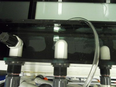
Yes: build a single large tank, to accomplish the stages you need, and use baffles for water movement between sections. Setups using pipes without a gravity advantage, seldom work as planned, especially in higher flow circumstances, for low flow they can be made to be adequate.
 
Uncleof6:

Thanks for the in-put, not much outside the box, but I know some don't like to go there. Thanks any way.............................Budster
 
First off: cut the pipes off, so that the outlets are less than 1" below the water level in the sump. (basic setup instructions)

The siphon capacity of a 1" line is right around 2000 gph w/36" drop, which is right where this tank should be running. So, I think you should be running a larger siphon--rather than pushing the limits of your siphon line.
Uncleof6:

My design plans call for this tank to run at about 1200gph, I will create more usefull flow in the tank with programable power heads. Back to the origional question, if a 1" line should carry 2000gph at full syphon, I wonder why mine is performing at a much reduced rate of about 1200gph. My pipes at the sump are cut off at about 1" to 2" below sump level (as I recall that was the recomendation in the basic set-up instructions). My ball valve is placed low on the 1" line. My syphon starts easily with no problems, I have vented the open line with a threaded fitting and 3/8" poly line, the open channel will syphon readily when the poly line is closed. All seems to be working as advertised, just not the capacity you claim. If you have any ideas I would be interested in hearing them, maybe Bean would chime in on this one too.
.....................Budster (See pictures in next post)
 
Last edited:
Pictures

Pictures

These pics. may help find the problem!
 

Attachments

  • 011.jpg
    011.jpg
    50.5 KB · Views: 3
The 1" pipe will incur friction losses. Lets assume it is #40 pipe that has an effective ID of about 1". WITHOUT accountinf for friction loss, and gravity alone, at 36" the max theoretical flow is about 2000 GPH. at 24" it is 1600 GPH.

Assumung the union has a slight restriction, as does the fully open ball valve, and the friction of the pipe and that added by the bends, intake angle, etc. 1200 GPH max is right in the ballpark.

Thanks Bean: One question would be, can I gain any flow by increasing pipe size from the hole in the glass down to the sump (union, ball valve and pipe) leaving the plumbing on the aquarium side of the glass at 1"?

Thanks again for your help.........................Budster
 
This is what I am planning...let me know if you see any issues. This is for a drilled bottom tank with one overflow in tank for a 165 gallon with 80 gallon sump.

1. I will have a 1.5" drain straight pipe (this is the vacuum drain) with a gate valve below to control drain speed. This will be the lowest drain.

2. The next drain will be a 1.5" durso drain pipe with a hole in the durso in the side to allow air in. This drain will have very low flow so hopefully will make no noise. This drain will be higher than the vacuum drain above. As this drain has no gate valve, and is wide open, it should be able to drain all water if the #1 drain plugs.

3. The 3rd drain is a 1.5" emergency staright pipe drain just like #1 above, which should turn into a vacuum drain just like #1 above if the other 2 drains get plugged.

Let me know if this will work fine and will be quiet.
 
Thinking of upgrading from a crammed 55g sump to a 75

I had designed another 55 and then decided to go to the 75.

Does this LQQK like it will work? I’m running a BA drain system. I did not want a long horizontal run and have read that the BA does not do well. So I’m thinking of moving them from draining in the right side of the old 55 and then in the right side of the middle area.

Will there be enough turbulence to churn the water with just the 2 drains 1” under water? It will then flow to the left and through 2 filter socks. It will dump in the sump close to the PS and then flow to the right and out through the external pump. Then I will have a spray bar in the fuge area pointing to the left to create some movement to the left and up and over to the right. The spray bar will get its water from the external pump.

My current sump flows right to left with the sump in the middle.
2012-09-14_12-06-48_657.jpg~original


Updated 55 drawing.
55sumpwronwb150.jpg~original


New 75g design.
75sump.jpg~original
 
Last edited by a moderator:
eagle9252,

As far as the drain lines are concerned, it is true a horizontal run in the lines could cause issues with the startup of the system, and possibly some noise from the open channel. However, running the lines at a 45° angle, will move the drain lines to a more convenient location, and will not affect the operation of the drain system.

Outlets for this drain system, need to be 1" or less below water level, for proper operation (startup) of the system. I am not sure what you are getting at with "churn the water" however.

As far as the sump flow logic and operation, that is pretty far off topic for this thread, and would probably be best dealt with in a sump design thread, or its own thread. :)
 
Churning meant the rotation / flow or turn over inside the drain box. Would the velocity of the water with the pipes just 1"under the surface cycle the water in the drain box
 
Yes, depending on the flow rate. But even if it did not, you do not want the outlets more than 1" below the water level.
 
I just check my local Lowes (preparing for BA setup in 90 g) and there are no sanitary Tees in the schedule 40 section (Im doing 1", but there weren't any..not even a shelf place for them). Is this normal? I assume a sanitary tee would be much better but can I use a normal Tee at the top of the three downpipies?

Should I bother checking HomeDepot or will I see the same thing there?

They don't make sanitary tees smaller than 1.5". You will not find them at Home Depot either. Regular tees will work fine, the sani tees just cause less turbulence.

Also, I would use 1.25" for the open channel. 1" open channels will be a bit touchy ( a very low laminar flow capacity.)
 
They don't make sanitary tees smaller than 1.5". You will not find them at Home Depot either. Regular tees will work fine, the sani tees just cause less turbulence.

Also, I would use 1.25" for the open channel. 1" open channels will be a bit touchy ( a very low laminar flow capacity.)


Well I had to look up "laminar" so now I get what you're saying. Does that issue have anything to do with the overall flow? i.e. If im running well under pipe capacity (600gph) of the siphon.

Thanks for saving me a trip to HD.

Oh, and I just though of this...is there some point where the downpipe is too big relative to the return pipe (less head) such that I can create a siphon and successful BA setup? I mean I'll go bigger but I figured it was overkill and more glass stress (bigger holes) for no upside (plan on flow of 500-800).
 
Has anyone extended the pvc pipe between the tank bulkhead and the sanitary T so that ball valves and rest of the plumbing is all on the other side of a wall (in the fish room)?

This question is from an old post but I couldn't find an answer. I too plan on running straight out of the tank for about 6-7" before hitting the Tee. Is this ok?
 
Back
Top