Silent and Failsafe Overflow System

Thickness of Glass on External Overflow Box

Thickness of Glass on External Overflow Box

I'm using a BeanAnimal Design on a 75-gallon tank, which utilizes both an internal overflow box (weir) and an external overflow box. Both overflow boxes are the width of the tank, 48 inches. The external overflow box = 48" wide x 8" tall x 5" front-to-back.

Question: is it sufficient to use 1/4" glass for the external overflow box, on all its pieces--sides, bottom, and front, or should I use 3/8" glass at the bottom of the external overflow box, using 1/4 on the sides and front? Has anyone ever used an external overlfow box on a BeanAnimal design using only 1/4" glass, with a width as wide as 48"? I will be using glass triangles for supports, such that one edge of each triangle will be siliconed to the back of the tank, and the other to the bottom of the overflow box. Perhaps such extensive support might permit me to use only 1/4" glass. What do you all think?

Thank you.
 
Does it make any difference if the valves are down in the stand instead of behind the tank?

Thanks,
Paul

As shown in this voluminous thread, people have done it both ways. They have placed the TruUnion ball valve up top, behind the tank and somewhat adjacent to the bulkhead, and others have placed it down low, above the termination points in the sump. Scroll through the thread and look at people's pictures, and you'll see this is the case. Although my sense of things is that more people place it up top, than down below. Good luck!
 
Last edited:
Do the standpipes have to be glued into the bulkheads inside the overflow box? I usually never had my stand pipes glued into the bulkheads but it seems that this system must be airtight in order to work. Will not having them glued in affect the performance?
 
Do the standpipes have to be glued into the bulkheads inside the overflow box? I usually never had my stand pipes glued into the bulkheads but it seems that this system must be airtight in order to work. Will not having them glued in affect the performance?

Piping outside the tank has to be secured, preferably by PVC Cement, which "welds" the separate PVC components together; others use threaded connections. If you are talking about the elbows inside an internal overflow box, behind the weir, then, no, they should not be cemented to the bulkhead inlet; it's safe just pressed into the bulkhead, and you have the freedom to move them around, inside the internal overflow "trough." Good luck.
 
As shown in this voluminous thread, people have done it both ways. They have placed the TruUnion ball valve up top, behind the tank and somewhat adjacent to the bulkhead, and others have placed it down low, above the termination points in the sump. Scroll through the thread and look at people's pictures, and you'll see this is the case. Although my sense of things is that more people place it up top, than down below. Good luck!

Thanks for the help!
 
Piping outside the tank has to be secured, preferably by PVC Cement, which "welds" the separate PVC components together; others use threaded connections. If you are talking about the elbows inside an internal overflow box, behind the weir, then, no, they should not be cemented to the bulkhead inlet; it's safe just pressed into the bulkhead, and you have the freedom to move them around, inside the internal overflow "trough." Good luck.

Thanks for the reply. What is the reason one would place the bulkhead near the sump? I have my sump in the basement and I want to do this to slow the water down before it hits the sump, however tuning will be really hard because I will have to run up and down the stairs all the time.
 
Thanks for the reply. What is the reason one would place the bulkhead near the sump? I have my sump in the basement and I want to do this to slow the water down before it hits the sump, however tuning will be really hard because I will have to run up and down the stairs all the time.

The bulkhead is always placed in and through the hole in the glass, where water passes through. I think your question meant to ask why do people place the valve on the drainline near the sump or near the bulkhead up top, as the case may be.

If that is your question, then I suspect that most people would position the valve at a convenient location. For me, I have a design that calls for the greater convenience to access the valve below, near the sump. Here is why: the back of my aquarium will be housed in a hutch of sorts, which conceals the piping from sideviews.

Here are some Google SketchUp drawings that I've been working on for some time now, which are still incomplete. As you will plainly see, the cabinetry of the hutch is not yet depicted in these drawings. You have to use your imagination: imagine that side, back, and top panels will obscure everything from the back glass of the aquarium, going backward to the back edge of the aquarium stand. Given that the PVC behind the tank will be covered in a cabinet-hutch, I won't have ready access to the valve, to fine-tune adjustments, without removing the hutch. Although the hutch is removable and will have a pop-up top, like an upright piano, and it will have pop-out sides, I would rather have the convenience of turning the gate valve of the siphon drain line from below, inside the aquarium stand.

2012-12-9AquariumStand.jpg~original


This is the front view. You can see the red knob of the gate valve, positioned on the siphon drain line.


2012-12-9AquariumStand2.jp~originalg~original


This is the back view. You can see the red knob of the gate valve again, positioned on the siphon drain line.


2012-12-9AquariumStand3.jpg~original


Another backside view: imagine that the external overflow box and the piping will all be covered up in a cabinet-hutch. Having the valve there would be quite inconvenient.

2012-12-9AquariumStand4.jpg~original


Here is a front shot, depicting the internal overflow box (black) which passes water over the weir and through the back glass of the aquarium to the external overflow box, through 5 pass-through holes. Use of a skinny internal overflow box here, reduces the obtrusive profile of a deeper (front to back), fully-functioning internal overflow box with the PVC elbows.
 
Last edited by a moderator:
The bulkhead is always placed in and through the hole in the glass, where water passes through. I think your question meant to ask why do people place the valve on the drainline near the sump or near the bulkhead up top, as the case may be.

If that is your question, then I suspect that most people would position the valve at a convenient location. For me, I have a design that calls for the greater convenience to access the valve below, near the sump. Here is why: the back of my aquarium will be housed in a hutch of sorts, which conceals the piping from sideviews.

Here are some Google SketchUp drawings that I've been working on for some time now, which are still incomplete. As you will plainly see, the cabinetry of the hutch is not yet depicted in these drawings. You have to use your imagination: imagine that side, back, and top panels will obscure everything from the back glass of the aquarium, going backward to the back edge of the aquarium stand. Given that the PVC behind the tank will be covered in a cabinet-hutch, I won't have ready access to the valve, to fine-tune adjustments, without removing the hutch. Although the hutch is removable and will have a pop-up top, like an upright piano, and it will have pop-out sides, I would rather have the convenience of turning the gate valve of the siphon drain line from below, inside the aquarium stand.

2012-12-9AquariumStand.jpg~original


This is the front view. You can see the red knob of the gate valve, positioned on the siphon drain line.


2012-12-9AquariumStand2.jpg~original


This is the back view. You can see the red knob of the gate valve again, positioned on the siphon drain line.


2012-12-9AquariumStand3.jpg~original


Another backside view: imagine that the external overflow box and the piping will all be covered up in a cabinet-hutch. Having the valve there would be quite inconvenient.

2012-12-9AquariumStand4.jpg~original


Here is a front shot, depicting the internal overflow box (black) which passes water over the weir and through the back glass of the aquarium to the external overflow box, through 5 pass-through holes. Use of a skinny internal overflow box here, reduces the obtrusive profile of a deeper (front to back), fully-functioning internal overflow box with the PVC elbows.


Thanks. My overflow box is external but is drilled on the bottom. I was going to have the "T" Inside my overflow box and then have the 90 degree elbow connected to it. I tried this yesterday and it wont fit. Once I add the "T" and the elbow it's too big for the box. Would I have any issues just using 2 elbows instead of a "T" and an elbow? Two elbows are a little narrower and it just fits. I can drill a hole in one elbows for the john guest fitting. I just would have the caps for cleaning but I don't think I would use those anyway because I am not planning on gluing the stand pipes into the bulkheads inside the overflow box. SO I can always just pull them out for cleaning if needed.


Thanks,

Adam
 
Last edited by a moderator:
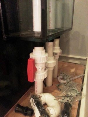
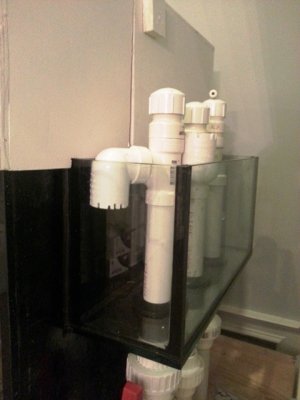
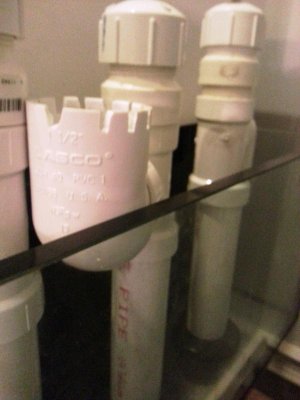
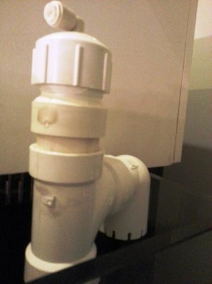
This is how I did my mine. I hope it works let me know if you see any issues. I also don't know how high the stand pipes need to be in the over flow box. They are all cut very high for now.
 

Attachments

  • 20121210_231058.jpg
    20121210_231058.jpg
    36 KB · Views: 4
  • 20121210_231101.jpg
    20121210_231101.jpg
    96.4 KB · Views: 3
  • 20121210_231107.jpg
    20121210_231107.jpg
    45.3 KB · Views: 3
  • 20121210_231111.jpg
    20121210_231111.jpg
    26.7 KB · Views: 4
This is how I did my mine. I hope it works let me know if you see any issues. I also don't know how high the stand pipes need to be in the over flow box. They are all cut very high for now.

I suspect you will lower them. You could probably lower the down-turned elbows to about 1/2 inch above the inside bottom of the overflow box, and, of course, the up-turned, dry-emergency elbow will have to be below the top of the overflow box, with room to spare.

BeanAnimal used some very interesting mathematics to explain it all in this thread, at Post No. 3223:

[By BeanAnimal in Post No. 3223] The area created by the distance between the bottom edge of the elbow should be at least (or greater) than the cross-sectional area of the elbow. So for example: lets assume a 1.25" elbow with an inside diameter of 1.66". The cross section area is .83" * .83" x 3.14 = 2.16 square inches. Instead of measuring the OUTSIDE diameter of the pipe, lets just use the inside diameter to make life easy for the next part. This will also add in our fudge factor to get a bit of extra spacing to account for surface tension, turbulance, etc. We know that the circumference of the circle is 1.66" * 3.14 = 5.21". So if we divide the needed area (2.16 sq in) by the circumference (5.21") we get 2.16" sq / 5.21" = .41". So your elbow needs to be at least .41" off of the bottom to prevent a flow restriction. So .5" should be fine. [He slightly modified his response a few posts later, but you get the idea.]
 
I thought I would post an update on my overflow as I am having some issues and really need some help.

Back on page 186 I describe my system and problem:
I think the problem is the horizontal run of the pipe. It goes down five feet from the bulkhead, then runs about 7 feet horizontally, then down into the sump.

The problem: the overflow works perfectly, except when I try to start the siphon/turn off the pump/power outage. After these events the siphon does not start due to the lowish flow (900 gph) and the gate valve being nearly closed to support the proper water level in the overflow box. Siphon starts fine with gate valve open.

I added a tube to the top of the full siphon line just like the open channel with a valve. This way when I start the pump, a little water and air goes down the siphon. Then I shut the valve and the siphon flows normally.

This is not ideal.

I need to know what I should do. As I see it I have three options:

1. Get a bigger pump to push more water down the siphon. This would allow me to open the gate valve more and allow the siphon to start easier.

2. Change out the 1" siphon plumbing and go 3/4". Thought being less air to push out to start the siphon and allowing gate valve to open more.

3. Try a different plumbing method.

Any help much appreciated.

4): Eliminate the horizontal run, and quit fighting with it.

1" is the smallest plumbing you want to use.

You probably need a bigger pump anyway, but don't recall the size of the tank. Friction loss in the return line is probably killing you anyway. It is a cumulative effect.
 
Any ideas how i can fix air bubbles forming over my coast to coast? The water "drops" about 3 1/2" before it hits the water in the box somehow causing air bubbles to form and they are being sucked into the siphon causing noise.
 
> fix bubbles forming over my coast to coast?

the simplistic "eliminate horizontal runs" answer that is 100% correct but totally useless is: "slow the flow" a few tricks are:
  • restrict the pump output and hence the flow over the weir.
  • reduce the height the of the fall over the weir.
  • quarter round the top of the weir to keep the flow attached and laminar on the weir.
  • increase the depth of the basin so the flow can stay laminar longer and not upset the surface of the basin.
  • flatten the weir so it takes more time (lower speed) to reach the basin.
    p094a.gif

  • fill the c2c with sponge to widen the flow (lower speed)
if there is an air gap at the top of the weir, drill some holes no larger and a tad higher than the gap. This will reduce your surface skimming, but will keep the flow attached to the weir.

Let us know what ends up working for you!
 
Last edited:
The simple answer to the bubbles in the overflow is: raise the plumbing and the water level. Both are too low in the overflow, otherwise there would be no bubbles. The water should only drop around an inch or so. Simple.

Incidentally, stuffing sponge in the overflow is a pretty poor idea. As soon as crud gets trapped in it, (which will rot by the way) it will change the flow characteristics of the system. The point: don't mess with the drain system--period.
 
The only way i know how to raise the plumbing is cutting the bottoms of the down turns and raising the bottom of the overflow box. Closing my main siphon valve more (to raise water level) just results in the secondary trying to flush the water.
 
My current tank is a 75 and I am upgrading to a 93 cube.

Uncle you are thinking more flow, allowing the gate to be open more will help my problem?
 
Took your advice

Took your advice

From a PM: (note: please don't PM me questions, it is too much work to manage the thread and PMs.)


Not sure why you want an "internal" overflow plumbed through the bottom of the tank, but the physics and operation of the design are not affected. The design (as published) is capable of a wide range of flows. What is your proposed return pump?

Thanks for the reply bean, I totally agree and have decided to just follow your design.
Like the other poster mentioned, I was trying to eliminate the space needed behind the tank, but the benefits to the shallow box and external plumbing is what I want.
 
Back
Top