You are using an out of date browser. It may not display this or other websites correctly.
You should upgrade or use an alternative browser.
You should upgrade or use an alternative browser.
Silent and Failsafe Overflow System
- Thread starter JohnL
- Start date
It is definitely possible I'm getting air from the internal elbow as it is not glued at all. Should I glue it with PVC cement?
I'll see if I can find some teflon past for the cap. I'd like to get to the bottom of this. Hope I'm getting closer!
I used two wraps of Teflon tape around the slip side of the elbow to eliminate this. It worked for me.
BeanAnimal
Premium Member
Don't cement that elbow... it will eventually seal itself, but as jerpal indicated a wrap or two of teflon to snug it up will work, as would a smear of silicone lubricant (fthe stuff for faucet washer, etc).
uncleof6
Active member
So I figured I should possibly move my problem over to this thread since it gets a bit more attention than a problem thread from some random new guy. Thank you all for any suggestions in that thread though.
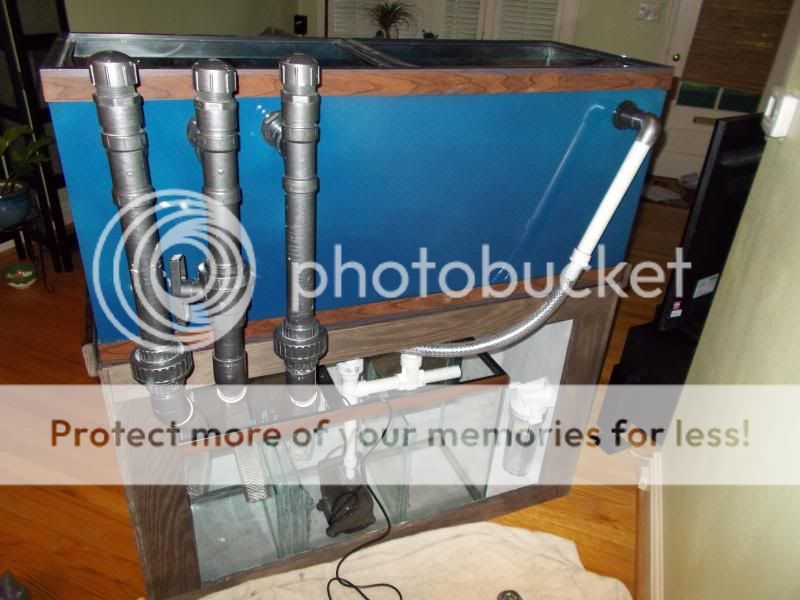
I have built a coast to coast overflow box with a beananimal drain system. It's a 1.5" drain with a 1" return. I have the system up and running, but somehow I cannot get a full siphon out of the siphon tube. I hear water gurgling down the pipe and it is ejecting bubbles into my sump. The ball valve is adjusted so the water level is about 3/4" of the way up the intake pipes. There is a slight trickle of water coming out the open channel drain. I upgraded my pump to a mag 18 hoping low flow was the issue, but the noise remains. Some people have suggested going down to a 1" drain system, but that would be a whole lot of work to change and the system was designed as a 1.5" system.
It seems like air is entering the siphon pipe somehow, I just cannot figure out where. The cap is screwed on with teflon tape. My thought is possibly air is getting in at the ball valve. I just don't know where or how?
Here is a photo of the system. Since that photo I have changed the siphon tube to all pvc down to the sump. I will be supporting all the tubes so they don't put pressure on the bulkheads. I was just figuring out how to do it. Also I will be adding the flexible tubing to the top of the open channel system for the ultimate safety.

Rather than involve myself in the debate over teflon tape/paste/dope blah blah, the intended purpose for each, and why they aren't supposed to be used with plastic fittings, I will let Lasco do the talking:
http://www.lascofittings.com/supportcenter/TheDosandDontsThreadedPlastic.asp
Now that all that is over with, onward.
You took some bad advice on the pump. As you found out it was not the solution, and never would be. A bigger pump is always good for the system however. On the other hand though, with that small return line (1") you are not getting the flow out of that pump, that you would think. The mag drive pumps 9.5 and larger, require 1.5" pipe for the return, to get any flow out of them (it is in the instructions.) Their design is flawed; they are hot and noisy. You are just wasting electricity using 1" pipe.
The real issue is, that you could be sucking air into the siphon line, from any point in the line—from the elbow down to the outlet. The likely culprets are: the intake elbow and the threaded cap join—both tape rather than a thread sealant, + over tightening, the union ball valve no o-ring lubricant (Silicone grease) + over tightening = damaged o-rings, or any of the glued joins in the drain line. You can test for air leaks, by putting some silicone grease around the join...
http://www.amazon.com/Pentair-R172036-Lubricant-Replacement-Chlorinators/dp/B004YLJAC0
(the Super Lube works just as well)
Looks to me like you painted the pvc. If so, did you paint it before or after it was assembled? Any paint at all on the internal or external threads or pipe/socket, and the joint is not going to seal—even with the best thread sealant, or best gluing technique.
jerpal
:facepalm:
Firochromis
New member
Hi people,
l know this is hard to answer but here it goes.
ln my 180g tank l'll use a 2500g pump in a manifold, which will also feed some reactors and frag tank. l'm expecting half of that 2500g in my tank. My drains are 1.5" and my return is 1".
So, i have a 1.25" true union valve already in hand. Since the valve in siphon line is reduced, do you think is it safe to use this 1.25" valve on the 1.5" line? Or am l too cheap?")
l know this is hard to answer but here it goes.
ln my 180g tank l'll use a 2500g pump in a manifold, which will also feed some reactors and frag tank. l'm expecting half of that 2500g in my tank. My drains are 1.5" and my return is 1".
So, i have a 1.25" true union valve already in hand. Since the valve in siphon line is reduced, do you think is it safe to use this 1.25" valve on the 1.5" line? Or am l too cheap?
A 1.25" siphon line with a drop of 3 feet will still flow 3100 gph so it will work.
There is a handy calculator at the bottom of this wordy article.")
Hydraulics for the Aquarist
There is a handy calculator at the bottom of this wordy article.
Hydraulics for the Aquarist
uncleof6
Active member
A 1.25" siphon line with a drop of 3 feet will still flow 3100 gph so it will work.
There is a handy calculator at the bottom of this wordy article.
Hydraulics for the Aquarist
The calculator calculates the maximum theoretical flow, through an OPEN bulkhead, with no pipe attached, at the given drop. Due to friction loss in the plumbing, the numbers are actually somewhat lower. There is more to it, than just spinning the numbers. These numbers are approximate, and do not account for friction loss. When pushing above 2000 gph, it is far better to use 1.5" pipe--valve in hand or not. A gate valve would be a better choice anyway.
Firochromis
New member
The calculator calculates the maximum theoretical flow, through an OPEN bulkhead, with no pipe attached, at the given drop. Due to friction loss in the plumbing, the numbers are actually somewhat lower. There is more to it, than just spinning the numbers. These numbers are approximate, and do not account for friction loss. When pushing above 2000 gph, it is far better to use 1.5" pipe--valve in hand or not. A gate valve would be a better choice anyway.
Thank you uncle. l was already planning to use 1.5" pipes in this line with a 1.25" valve. But if you suggest a 1.5" valve, than better to buy a gate valve rather than a ball valve.
BeanAnimal
Premium Member
Kinda (I know you know, but I will spell it out for those who don't)The calculator calculates the maximum theoretical flow, through an OPEN bulkhead, with no pipe attached, at the given drop.
It calculates gravity driven flow from point A to point B based on the NET vertical drop, in or out of a pipe. It does so without consideration to friction loss in the pipe. So the if the water travels UP 6 feet in a pipe, before it drops 7 feet, then the static head is 1 foot... and that is what is calculated.
Key distinction, if we are making distinctions
100% correct... I am lazyThese numbers are approximate, and do not account for friction loss.
BeanAnimal
Premium Member
Thank you uncle. l was already planning to use 1.5" pipes in this line with a 1.25" valve. But if you suggest a 1.5" valve, than better to buy a gate valve rather than a ball valve.
The 1.25" valve will be fine, but at the same time, you might as well use the 1.5" valve.
As for gate vs ball... I still rely on quality full port ball valves. Though some folks like the adjustability of the gate valves, I have not found the need in my setups. I also tend to end up with leaky stems when I use them in SW applications.... That said, I have never used one on the overflow setup so coudl/would be blissfully ignorant of any added benefit.
ErryDayImReefin
New member
I love the BeanAnimal style overflow, I ran this on my 220 for years, but now I have a smaller tank and in the process of building a frag system. How would this work for two 40g breeders and a 60g deep blue frag tank (already drilled) running on the same sump/refugium filtration system? I feel like it would be crowded with pipes and that the flows might be thrown off a bit considering I plan to gravity feed a chiller and a skimmer from 2/? drains.
Greatly appreciate your help and advice! Awesome work from all of you!
Greatly appreciate your help and advice! Awesome work from all of you!
No. But I will tell you the minimum distance from the top of the glass to the CENTER of the hole: 2 3/4". Another half inch won't hurt either.
I run the weirs on rimless tanks 1" below the top edge of the glass. The drain system is reliable and safe.
Thanks Uncle... My overflow box is 15"Lx5"Dx6"H. It's made of glass. On the outside of it, I've glued on a black acrylic shell to cover the glass. (so you can't see into the overflow) The top of the acrylic shell has 1" tall "fingers" to keep the fish out of the overflow making the total height 7". You mentioned my overflow should be 1" below the top edge of the glass. Correct me if I'm mistaken, but the 1" starts from the top edge of the glass to where the water enters the overflow... correct? So in my case, the 1" fingers would be even with the top edge of the glass? ( I hope I'm not being a pain in the *** with this, but I'm getting ready to do this. You mentioned prefab overflows are not adequate. Is my overflow box big enough, you think, to allow in enough water for the drain system to work?
Thanks
I had my emergency kick on a couple weeks ago, and I couldn't figure out why. I unscrewed the cap and used a push rod down the siphon pipe to see if there was anything in there. I pushed out three cerith snail shells. Each shell was about an inch long and had gotten stuck at the union. The system worked EXACLTY like it was supposed to. Thanks BA and uncle for all your knowledge and dedication in helping everyone along the way, truely reef ambassadors.
Here is what I started using again on this tank that I have used on other tanks to help prevent shells from getting in the drains.

Drilled four small holes about 1/8th inch from the end on all three inlets. My lines are only an inch, obviously for larger diameter you may want to drill more holes and run more fishing line.
Here is what I started using again on this tank that I have used on other tanks to help prevent shells from getting in the drains.
Drilled four small holes about 1/8th inch from the end on all three inlets. My lines are only an inch, obviously for larger diameter you may want to drill more holes and run more fishing line.
Well I would find some way to eliminate the teeth, and place the "straight" "flat" weir, 1" down from the top edge of the glass. Teeth, reduce the surface skimming efficiency by 1/2 to 2/3. Not a good thing&madash;and they don't keep the fish out of the overflow.
Great... That's easy enough to do. I'm still hoping my box is big enough to allow enough volume. One final question. I planned on a running a DC 12000 pump, when they're finally released. That pump has a 1.25" output and is capable of over 3000gph. I planned on splitting it off into two 3/4" returns. Inside my overflow are three 1.25 to 1" elbows. Everything else from the other side of the bulkhead to the sump will be 1.5". Going by your comments to Ciwyn: "A bigger pump is always good for the system however. On the other hand though, with that small return line (1") you are not getting the flow out of that pump, that you would think."
Suddenly my dual 3/4" returns seem anemic.
It's a 90gal tank. What would you suggest for my returns?
Last edited:
uncleof6
Active member
They are anemic to be honest. It is a hard point to make, but 3/4" is not really suitable for marine systems. They are just too small, too easily plugged, and friction loss is extreme. For returns go one size up from the actual pump outlet size, in most cases. In any case, don't go below 1". Notable exception is the Danner Mag Drive pumps 9.5 and over. They require 1.5" return plumbing. (Per instructions.)
External pumps have an additional requirement: If the outlet pipe is larger than the intake volute size, the intake pipe from the sump must also be upsized to the same or larger size as the outlet pipe. This helps prevent cavitation. Submersible pumps don't have this requirement, as the "intake pipe" is the size of the return section of the sump.
External pumps have an additional requirement: If the outlet pipe is larger than the intake volute size, the intake pipe from the sump must also be upsized to the same or larger size as the outlet pipe. This helps prevent cavitation. Submersible pumps don't have this requirement, as the "intake pipe" is the size of the return section of the sump.
GROSSR
Active member
wonrib00 : I open my valve every few weeks just to make sure. I travel about 90% of the time and when I get home I hear this gurgling sound, water level in the overflow is higher than normal, I open the valve, start to adjust it and the noise is gone. Snails are usually the culprit.
Uncle6 : I have 3/4" all around. I only have a 46 bow with a eheim 1260 and my valve is turned down quite a bit to match the pump. More than I would have thought.
rich
Uncle6 : I have 3/4" all around. I only have a 46 bow with a eheim 1260 and my valve is turned down quite a bit to match the pump. More than I would have thought.
rich
dirtycontour
New member
Hey guys, quick question. Is this enough clearance for my siphon drain?

Last edited by a moderator:
Similar threads
- Replies
- 3
- Views
- 254
- Replies
- 2
- Views
- 1K
- Replies
- 4
- Views
- 1K