You are using an out of date browser. It may not display this or other websites correctly.
You should upgrade or use an alternative browser.
You should upgrade or use an alternative browser.
Silent and Failsafe Overflow System
- Thread starter JohnL
- Start date
uncleof6
Active member
Got it...... I understand that. I never had good luck putting a fitting in cap. Teflon tape helps but not well. What is the preferred method here?
A slightly oversized hole (very slightly) as in 64ths, and iron pipe with the proper threads to tap it, is one way to do it. I use the proper drill bit size, (the drill bit is flat ground for use on acrylic so it does not chew up the plastic,) the proper tap, and a non-hardening thread sealant. I don't run the tap all the way in, so it is a little tighter, and you are not supposed to use tape on this type of thing anyway...buy some chinese import caps (cheap) and practice, you will get the hang of it
")
EDIT: Probably the hardest part of the process is getting the hole dead center on the cap. If it is off center, it will not seal as well...in the image above, done in a hurry, the hole is off center...
Last edited:
hbash
New member
1/4" JG Fitting etc.
1/4" JG Fitting etc.
I ordered the fitting recommended at H20 using this URL as specified:
http://www.h2odistributors.com/pi010823s.asp
Can you point me at a URL to get the tapping bit(s)?
Thanks
1/4" JG Fitting etc.
I ordered the fitting recommended at H20 using this URL as specified:
http://www.h2odistributors.com/pi010823s.asp
Can you point me at a URL to get the tapping bit(s)?
Thanks
uncleof6
Active member
I ordered the fitting recommended at H20 using this URL as specified:
http://www.h2odistributors.com/pi010823s.asp
Can you point me at a URL to get the tapping bit(s)?
Thanks
http://www.mcmaster.com/#2525a114/=u30dmc
http://www.mcmaster.com/#27465a73/=u30f28
The drill bit is going to hurt a bit....
hbash
New member
Diagram Update
Diagram Update
I look forward to the updated diagram when time permits of course.
Thanks!
Diagram Update
Well that is the wrong diagram if that helps at all... you have some time before you really need to know (I think) so tomorrow I will work something up for you, but it is going to be close to the above. That diagram is the one for internal/external system... sorry it has been a long day, and even college students act like children at times....
Depth of the overflow is irrelevant, if that helps. Once setup and adjusted, this system is super reliable (200+ of them most of them converted from other drain systems.)
I look forward to the updated diagram when time permits of course.
Thanks!
uncleof6
Active member
I look forward to the updated diagram when time permits of course.
Thanks!
The U shape represents the space between the teeth (or fingers) adding these spaces up, gives you the effective length of the weir, the top of the U shape is the top of the overflow (1.5")
The 1 7/32 is ~ the distance to the top of the elbows, and the other dimension is the distance to the elbow centerline... Water level in the tank (static) is at the bottom of the U shape, water line in the overflow is between the top of the elbow and the elbow centerline. You can tighten up, there is some room above to play with (1.5"...) or you can put them lower if you want.... it is not a space vehicle

adamwheel
New member
3 things:
1. The silent overflow works flawlessly. Snails bother me sometimes but that goes with the territory. Don't even remotely question it. Drill the holes in the right places and be happy you subscribed to this thread.
2. Tank Transfer your fish. Healthy fish are fun to watch (sick ones are not).
3. Uncle of 6 deserves a lot of credit for replying to the same exact questions over and over (and the rare question that makes him think). He can be a little demanding but I am very happy I listened to so many of his words. He's never steered me wrong.
Sorry. I know a little now and wanted to say thanks in the right forum.
Cheers,
Adam
hbash
New member
Question about the numbers. If this figure is for a 1.5" elbow I must be missing something. Isn't the difference between the two numbers pointing to the notch 2 19/64 - 1 14/64 = 1 5/64" too big? I would have expected .75" for the elbow top line to its center.
Forgive me for the silly question, but my forte' isn't drafting.
Thanks.
Forgive me for the silly question, but my forte' isn't drafting.
Thanks.
shermanator
New member
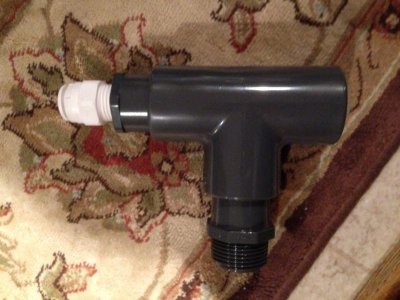
I'm hopefully going to drill my holes tomorrow on 40B. My plumbing is 1" sch 80, which I figure (hope) will be fine for a 40B.
I have a question about a change I want to make to how the mur-lok fitting is added to the open channel. Would it be okay to do something like the photo attached? I have read elsewhere that using a standard tee is okay, so I hope that is actually OK because I couldn't find a sanitary sch 80 tee in 1".
Thanks!
Attachments
uncleof6
Active member
Ummmmmmmmmm no it isn't: because the 1.5" is the inside diameter, not the outside diameter...for instance, the average ID of sch. 40 1.5" pipe is 1.592", and the average OD of sch 40 pipe is 1.9". In other words, the inside diamter of a sch 40 socket in a fitting is 1.9". The OD of a sch 40 fitting is not published. Use a tape measure and figure it out. This is getting a bit carried away here my friend...
uncleof6
Active member
I'm hopefully going to drill my holes tomorrow on 40B. My plumbing is 1" sch 80, which I figure (hope) will be fine for a 40B.
I have a question about a change I want to make to how the mur-lok fitting is added to the open channel. Would it be okay to do something like the photo attached? I have read elsewhere that using a standard tee is okay, so I hope that is actually OK because I couldn't find a sanitary sch 80 tee in 1".
Thanks!
Should not be an issue, but I have to ask why are you using sch 80? The ID of sch 80 is smaller (thicker wall) than the id of sch 40, which influences the friction loss of the system (slows the flow.) The strength, and pressure rating, are absolutely unnecessary, and a real waste. I use SDR21 which has a larger inside diameter than sch 40, and a thinner wall. More than enough strength.
They don't make sanitary tees smaller than 1.25" in any sch, SDR, what have you, for either sch 40 or sch 80 pvc.
shermanator
New member
Should not be an issue, but I have to ask why are you using sch 80?
No rational reason whatsoever. Being a noob and reading about how the sch 80 valves are awesome, I figured I should go all sch 80. And I'm plumbing a basement sump to a finished basement and my wife said no white pvc. I now realize there are many other better, cheaper solutions. I'll know a lot more for the next build.
As always, thanks for the help uncle!

hbash
New member
Just got that tapper and bit to make the thread for the John Guest fitting. It is huge compared to the first set I picked up at HD. I guess the difference will be that the new 1/4" x 3/8" JG will be much heavier duty than what I had originally thought to use. The valve should arrive in the next day or so.
I have a question regarding the air hose and how to best configure that. I think it will be neater if I use two JG elbows to make the air hose turn and point the hose down to the overflow box with it terminating above the running water level (1/16th Inch above?). It just seems more precise than hanging a looping piece of air tube.
Any thoughts on this would be appreciated.
Thanks.
uncleof6
Active member
Just got that tapper and bit to make the thread for the John Guest fitting. It is huge compared to the first set I picked up at HD. I guess the difference will be that the new 1/4" x 3/8" JG will be much heavier duty than what I had originally thought to use. The valve should arrive in the next day or so.
I have a question regarding the air hose and how to best configure that. I think it will be neater if I use two JG elbows to make the air hose turn and point the hose down to the overflow box with it terminating above the running water level (1/16th Inch above?). It just seems more precise than hanging a looping piece of air tube.
Any thoughts on this would be appreciated.
Thanks.
Did I not tell you, that I saw no reason to go larger than 1/4"? You kept talking about 3/8"...
The air vent line should be "attached" higher than the inlet to the dry emergency. Any lower, and it will prevent the system from operating properly. On a rimmed tank, that would mean attaching it just below the lip of the trim....
hbash
New member
I don't think I suggested I wanted to increase the size of the air line. You provided me with three links which I assumed were for the correct sizes: the tapper, the drill bit and the valve:
At H20 the valve is "John Guest® 1/4" x 3/8" NPTF Male Connector (Acetal)"
At McMaster the tapper is "Tap For Pipe Threads, Light-use, 3/8 Npt Pipe Size, 18 Threads Per Inch"
and the bit is "Drill Bit For Plastics, 9/16", 6" O'all Length, 2.1" Drill Depth"
I hope you're not telling me that these are not what is suggested. It just appears that the fitting for the 1/4" air tube must be larger. I noticed that the one I had (from US Plastics) has a narrow threaded part, so I am assuming that this one (from McMaster as per link) has the thread size nearly if not exactly the same diameter as the barrel that the JG 1/4" comes out of explaining the increases in the sizes of the tap and the bit (also as per provided links).
Last edited:
Similar threads
- Replies
- 3
- Views
- 335
- Replies
- 2
- Views
- 2K
- Replies
- 4
- Views
- 1K