Silent and Failsafe Overflow System

I'm not worried about installing it physically I'm just trying to iron out the technical details.

I'm a sparky so forgive me but I vaguely remember cavitation from fluids class and I'm sort of confused why a pump would be designed with a 1" inlet/outlet if I need to run a 1.5" pipe inlet/outlet.

Well I am a C10 and a sparky journeyman as well, but the classes don't cover fluid dynamics, and designing pump fed plumbing systems. The sparky end is motor controls, and that is where it ends, and motors are a speciality with the electrical trade and require additional training beyond the "apprenticeship." :)

Pump fed plumbing systems are an engineering problem. With centrifugal pumps, the inlet/outlet size of the pump do not determine the size plumbing required. The size of the plumbing is determined by the requirements of the system. Even the size of the pump itself is based on the needs of the system, not what someone said would be good to use, or that is the pump you happen to have on hand, and it should be the LAST purchase for the system, not the first. The is one of the few cases inwhich the cart needs to come before the horse. There are things other than static lift (pressure head) that have to be taken into account. Among them are net suction head pressure available, net suction head pressure required, friction losses in the pipe, fittings, it can get very involved.

To keep it simple, and not delve into the math/physics wherefore and thouarts, it is a simple basic principle, and practice when plumbing in a centrifugal pump, to upsize the pump outlet pipe size one size above the actual outlet size of the pump. This cuts the friction loss in the outlet plumbing by 1/2 - 2/3 and it is generally closer to 2/3. However, if the outlet plumbing is larger than the actual pump inlet size, the inlet plumbing needs to be upsized as well, to the same size as the outlet or larger. Otherwise the pump will cavitate. This is independent of the "static lift" or pressure head on the pump. Under the tank or down in the basement, same same. It is the same for all centrifugal pumps, from the little 1/15hp and 1/8hp hobby pumps up to the 3hp pumps I run in some cases, and larger.

Many have a hard time grasping the concept, so you are not alone. One fella, (here on RC) was not getting any flow out of his pump up from the basement, running 1" pipe. A pump similar to yours IIRC (100HD, rated for 45'.) The static lift was 14'. After some "reverse engineering" it turned out the actual dynamic head on the pump was 42', just below shut off head.

This little factoid has been around as long as I have been in the business/hobby (36 years.) Why folks in the hobby ignore this I don't know. I am certain many are not aware of it; i know that many don't bother reading the instructions that come with their pump. Danner Mag 9.5 and above (sporting a nice little 3/4" outlet) require 1.5" outlet pipe to get any flow out of them. It is right there in the instructions. Reeflo, is more direct to the point, with their instructions and specifically state "The inlet and outlet size of the pump do not determine the pipe size needed."

You are right, though. It makes no sense to run 1.5" return plumbing and then reduce to 1" to go through a bulkhead for aesthetics. That is why you should not go through the bulkhead. That is how tank manufacturers think things should be done, not what fluid dynamics says how things should be done. :)

The max flow for a 1" drain may well be ~4000gph, at that drop, but the max reasonable for 1" pipe is ~ 960gph, otherwise you will get excessive friction losses, and some noise. I can't see you needing higher than 960gph, so a 1" drain is "ok..." However, you are going to have problems keeping a 1" open channel (durso) quiet with that long of a drop. This does not relate to the "pump fed" plumbing.

OH, almost forgot: 1.25" SDR-21 has a inside diameter > 1.25". ;)
 
Last edited:
Well I am a C10 and a sparky journeyman as well, but the classes don't cover fluid dynamics, and designing pump fed plumbing systems. The sparky end is motor controls, and that is where it ends, and motors are a speciality with the electrical trade and require additional training beyond the "apprenticeship."

Pump fed plumbing systems are an engineering problem. With centrifugal pumps, the inlet/outlet size of the pump do not determine the size plumbing required. The size of the plumbing is determined by the requirements of the system. Even the size of the pump itself is based on the needs of the system, not what someone said would be good to use, or that is the pump you happen to have on hand, and it should be the LAST purchase for the system, not the first. The is one of the few cases inwhich the cart needs to come before the horse. There are things other than static lift (pressure head) that have to be taken into account. Among them are net suction head pressure available, net suction head pressure required, friction losses in the pipe, fittings, it can get very involved.

To keep it simple, and not delve into the math/physics wherefore and thouarts, it is a simple basic principle, and practice when plumbing in a centrifugal pump, to upsize the pump outlet pipe size one size above the actual outlet size of the pump. This cuts the friction loss in the outlet plumbing by 1/2 - 2/3 and it is generally closer to 2/3. However, if the outlet plumbing is larger than the actual pump inlet size, the inlet plumbing needs to be upsized as well, to the same size as the outlet or larger. Otherwise the pump will cavitate. This is independent of the "static lift" or pressure head on the pump. Under the tank or down in the basement, same same. It is the same for all centrifugal pumps, from the little 1/15hp and 1/8hp hobby pumps up to the 3hp pumps I run in some cases, and larger.

Many have a hard time grasping the concept, so you are not alone. One fella, (here on RC) was not getting any flow out of his pump up from the basement, running 1" pipe. A pump similar to yours IIRC (100HD, rated for 45'.) The static lift was 14'. After some "reverse engineering" it turned out the actual dynamic head on the pump was 42', just below shut off head.

This little factoid has been around as long as I have been in the business/hobby (36 years.) Why folks in the hobby ignore this I don't know. I am certain many are not aware of it; i know that many don't bother reading the instructions that come with their pump. Danner Mag 9.5 and above (sporting a nice little 3/4" outlet) require 1.5" outlet pipe to get any flow out of them. It is right there in the instructions. Reeflo, is more direct to the point, with their instructions and specifically state "The inlet and outlet size of the pump do not determine the pipe size needed."

You are right, though. It makes no sense to run 1.5" return plumbing and then reduce to 1" to go through a bulkhead for aesthetics. That is why you should not go through the bulkhead. That is how tank manufacturers think things should be done, not what fluid dynamics says how things should be done.

The max flow for a 1" drain may well be ~4000gph, at that drop, but the max reasonable for 1" pipe is ~ 960gph, otherwise you will get excessive friction losses, and some noise. I can't see you needing higher than 960gph, so a 1" drain is "ok..." However, you are going to have problems keeping a 1" open channel (durso) quiet with that long of a drop. This does not relate to the "pump fed" plumbing.

Thanks. Well to be honest I purchased a Lifereef system and that is the pump that is "included". It looks like I may go with a Reeflo as I intended to do originally. I can address the return plumbing as luckily my tank has yet to have been built so I can always have one hole cut to use a 1.5" return.

So, then how would I go about keeping this thing quite as you say with a long run?

Also, by sparky I meant electrical engineer so feel free to geek it up. I've taken all those boring classes like fluid mechanics, thermo and the like :D
 
Well the pump came with it and didn't... or was it Schrödinger's cat walked into a bar and didn't... geeking it up takes too much energy and i am lazy...

Open channels have set operating principles. e.g. the 1/4 full of water thing, with calm air in the middle. Dropping a 1" open channel that far may get a bit turbulent, even with it being 1/4 full. Just bump the open channel up to 1.25" SDR-21...
 
One question I have is the dimensions of an external overflow box - my tank is as shown in my build thread, with an external overflow box of 84" long by 6" wide by 7" deep.

Most of the overflow boxes I've seen seem to be ~10" deep, and I was wondering if 7" was good enough. It seems to fit my plumbing ok, and it would work better for me for other reasons, but when you veer from the known-good path, it's best to check these things :)

Cheers
Simon

You want the inlets to the downturned elbows around 3/4" up from the bottom of the overflow, and the water line in the overflow (running) just below the tops of the elbows.

Personally, I don't think your plan is "safe" in terms of the plumbing hanging off the back of an overflow, hanging off the back of the tank. That plumbing should go out the bottom of the overflow box, with the plumbing well secured to the stand, to help support everything. In this case you may well need the whole 7" of the overflow depth, I am not certain of 10" however, as i don't have hands on the system.

In post #7453, this thread, you can see why 10" of depth might be useful, (water line is at the centerline of the through holes.) Your setup is using a notch, rather than through holes, so not really applicable. Make sure that notch is radiused at the bottom "corners" or you will have a cracked tank. :)
 
Last edited:
You want the inlets to the downturned elbows around 3/4" up from the bottom of the overflow, and the water line in the overflow (running) just below the tops of the elbows.

Ok, that's good to know. I currently have the inlets to the downturned elbows at ~9/16 off the bottom (I was shooting for 1/2"). I can raise them up by ~1/4" to make it 3/4" off the bottom.

When you say the water line in the overflow ought to be running just below the tops of the elbows - from looking at your template above, it seems you're saying the water-line will be 2 9/16 down from the weir level. If that's the case on my system, it's going to be only just above the bottom of the horizontal part of the downturned elbow. If the water level was only 1 9/16 down from the weir, it would be where you're suggesting it ought to be. I take it this isn't one of the self-tuning aspects then ?

For clarity, here's a view down the overflow trough with those two levels marked as guides...

tank-view-down-trough.png

I guess I *could* go with an 8" deep overflow...

One of the design-constraints is that I want it to look a lot larger than it really is, so the sides and back are going to be shadow-boxed (or possibly even LCD on the back). That's why I wanted the space between the pipes and the back/sides of the tank; it's also why I wanted no visible man-made things (so the spray-bar is out of sight above the viewing pane, the closed-loops will be hidden etc.)

The idea was that a 7" overflow box would make it less obvious that it was there, because the viewing pane is still 1" below that. Sure, you can look up at an angle, and you'd see stuff, but if you're looking at the tank from across the room, it's normally at a straight-ish angle, and the effect is (hopefully) to get a much deeper tank than really exists.

However, ye canae argue wit' the laws of physics... If the water-level requires more depth, then more depth it will get. I guess I was hoping it would "find its own level" and the 7" depth wouldn't be as important...

Personally, I don't think your plan is "safe" in terms of the plumbing hanging off the back of an overflow, hanging off the back of the tank. That plumbing should go out the bottom of the overflow box, with the plumbing well secured to the stand, to help support everything.

The plumbing is supported, but it's supported where the piping is horizontal, rather than where it's vertical. It's not particularly obvious in the image in the other thread, so here's a clearer picture of what I was intending:

return-support.png

I can certainly move the 45-degree sections further down and clamp the pipes on the vertical section instead, but I thought the weight would be better supported on the horizontal section.

Make sure that notch is radiused at the bottom "corners" or you will have a cracked tank. :)

I'll be sure to mention it to Derek @ Miracles - I'm supposed to be talking to him early next week :)
 
Ok, that's good to know. I currently have the inlets to the downturned elbows at ~9/16 off the bottom (I was shooting for 1/2"). I can raise them up by ~1/4" to make it 3/4" off the bottom.

When you say the water line in the overflow ought to be running just below the tops of the elbows - from looking at your template above, it seems you're saying the water-line will be 2 9/16 down from the weir level. If that's the case on my system, it's going to be only just above the bottom of the horizontal part of the downturned elbow. If the water level was only 1 9/16 down from the weir, it would be where you're suggesting it ought to be. I take it this isn't one of the self-tuning aspects then ?

For clarity, here's a view down the overflow trough with those two levels marked as guides...

If you noticed, I stated the drawing does not really apply to yours system, rather an illustration of why a 10" overflow depth might be needed. Actually, the "ideal" drop from tank to water level in the overflow is ~1", for silence.


I guess I *could* go with an 8" deep overflow...
Or more...

One of the design-constraints is that I want it to look a lot larger than it really is, so the sides and back are going to be shadow-boxed (or possibly even LCD on the back). That's why I wanted the space between the pipes and the back/sides of the tank; it's also why I wanted no visible man-made things (so the spray-bar is out of sight above the viewing pane, the closed-loops will be hidden etc.)

The idea was that a 7" overflow box would make it less obvious that it was there, because the viewing pane is still 1" below that. Sure, you can look up at an angle, and you'd see stuff, but if you're looking at the tank from across the room, it's normally at a straight-ish angle, and the effect is (hopefully) to get a much deeper tank than really exists.
I always find that "client" designed systems put aesthetics ahead of function. That is a bit reversed from what should be done. Minimizing things (the least intrusive possible) is generally going to create a performance hit, somewhere else in the system.

Spray bars are a waste of time and energy. They create excessive friction loss, and thus a performance hit for the pump...and from that the overall conditions in the system. Every bit as much a waste as reducing a 1.5" return line into a couple or three 3/4" loc-lines.

However, ye canae argue wit' the laws of physics... If the water-level requires more depth, then more depth it will get. I guess I was hoping it would "find its own level" and the 7" depth wouldn't be as important...
No you can't argue with physics, but you can use them to your advantage, or not...

The plumbing is supported, but it's supported where the piping is horizontal, rather than where it's vertical. It's not particularly obvious in the image in the other thread, so here's a clearer picture of what I was intending:

I can certainly move the 45-degree sections further down and clamp the pipes on the vertical section instead, but I thought the weight would be better supported on the horizontal section.

Be that as it may, I would still recommend you run the plumbing out of the bottom of the box, and yes that will require the box be deeper. I did one external along the same lines, pipes out the bottom. I put it next to a more "traditional BA setup" and honestly the difference was not worth the effort, and the client was sorry they invested in the process, though they were "thrilled" with the final product overall. :blown: Here is one on RC, I do believe Miracles was the builder... I could be wrong though...:

http://www.reefcentral.com/forums/showthread.php?threadid=1482007&perpage=25&pagenumber=1

I get the idea with the shadow box and all, but I am figuring a year or so down the road, keeping the back glass pristinely clean is going to become an unenjoyable chore...

Also, I would eliminate the horizontal runs, they affect different systems differently, so it is an unpredictable modification. The sweeps aren't helping really, and would use standard 45s to get under the stand, along with necessarily re-designing the support.

I'll be sure to mention it to Derek @ Miracles - I'm supposed to be talking to him early next week :)
I am sure Derek has thought of that already... if not, I would have to withdraw my recommendation of Miracles as one of the top builders anywhere.
 
We picked up the brand new tank today after selling the Oceanic 110.

I had the measurements pretty down for hole locations at 3" from top of the trim. I got this beast, and the trim is not 1 or 1.25". It is 1 13/16".

Do you think I'd be still ok at drilling 3" (hole center is 3")? Also since I no longer have a 1/2" glass middle brace, just the standard plastic strip, I don't have to worry about that.

I wasn't expecting trim to be bigger, but I guess that's what I get for not expecting a curveball somewhere.

Overflow box as planned is 48" long x 5.5" H x 4" W (Floor of the box is actually 5.25 considering the .25" acrylic).

Edit: Rough mockup has hole center 2.5" from the bottom of the trim. Factoring in 1.25" for the downturn elbow, gives me about 1.25" to the bottom of the overflow box.

How do those measurements sound to folks?
 
Last edited:
If you noticed, I stated the drawing does not really apply to yours system, rather an illustration of why a 10" overflow depth might be needed. Actually, the "ideal" drop from tank to water level in the overflow is ~1", for silence.

So, I'm good, then ?

I guess I'm confused over how the mechanics of the flow will work out. What's the starting point for deciding how it will work ? Is it that the water-level will be just below the downturned-elbow's top, or is it that the water-level will be governed by the pump flow-rate ? Or that there'll be a certain amount of drop over the weir ? Or what ?

If I knew what the "fixed" datapoint was, it might make it easier to work out how things will perform...

I always find that "client" designed systems put aesthetics ahead of function. That is a bit reversed from what should be done. Minimizing things (the least intrusive possible) is generally going to create a performance hit, somewhere else in the system.
Guilty as charged.

I'm not after a purist system. I want something that will look nice and fit in with the design ideals - if the cost of that is that I have to put more effort and energy into other areas to properly support the tank and its inhabitants, then sobeit.

Spray bars are a waste of time and energy. They create excessive friction loss, and thus a performance hit for the pump...and from that the overall conditions in the system. Every bit as much a waste as reducing a 1.5" return line into a couple or three 3/4" loc-lines.

No you can't argue with physics, but you can use them to your advantage, or not...
Well, by "spray bar", I mean the submerged loc-line outlets from the pump return - there's no actual spray.

Again, this is form over function (so I guess I'm going to be scolded again [grin]), but I'm reasonably sure there'll be enough flow in the tank - there's 3 Reeflo Darts providing flow, one on the return (guessing about 1500 gph after friction/head losses), and one on each of 2 closed loops (for a combined 7500 gph after similar losses). That's about 22x turnover per hour for 400G system, even with a lot of friction loss on the return.

Be that as it may, I would still recommend you run the plumbing out of the bottom of the box, and yes that will require the box be deeper. I did one external along the same lines, pipes out the bottom. I put it next to a more "traditional BA setup" and honestly the difference was not worth the effort, and the client was sorry they invested in the process, though they were "thrilled" with the final product overall. :blown: Here is one on RC, I do believe Miracles was the builder... I could be wrong though...:

http://www.reefcentral.com/forums/showthread.php?threadid=1482007&perpage=25&pagenumber=1
Apart from personal preference, is there any reason why you don't like the out-the-side idea ? I did spend quite a bit of time reading about the BA system before planning anything out, and (as far as I can tell), all I've done from his original design is move the overflow from the inside of the tank to the outside, as well as up the bulkhead sizes. His original design had the pipes coming out the back. I actually thought I was following the design pretty closely.

I get the idea with the shadow box and all, but I am figuring a year or so down the road, keeping the back glass pristinely clean is going to become an unenjoyable chore...
Well, I already have a tank which I keep the sides and back pristinely clean, and I have done so for the last couple of years. Horses for courses, and all that. Yes, it's a pain sometimes, but I think the effort is worth it.

Also, I would eliminate the horizontal runs, they affect different systems differently, so it is an unpredictable modification. The sweeps aren't helping really, and would use standard 45s to get under the stand, along with necessarily re-designing the support.
Noted. Will do. I'll move the gate-valve to just above the first 45 though, because I won't have room otherwise under the stand. It'll still be low-down (ish) so hopefully will still work well.

Cheers
Simon
 
Apart from personal preference, is there any reason why you don't like the out-the-side idea ? I did spend quite a bit of time reading about the BA system before planning anything out, and (as far as I can tell), all I've done from his original design is move the overflow from the inside of the tank to the outside, as well as up the bulkhead sizes. His original design had the pipes coming out the back. I actually thought I was following the design pretty closely.

Cheers
Simon

No personal preference to it. The pipes out the back as you have them, are too exposed to the knock factor that will take the overflow down...out the bottom tucks the plumbing farther in, thus not as susceptible to the knock factor.

If going to go to loc-line outlets, you may as well switch to a much smaller pump, because essentially, the friction loss will kill your flow. That is fluid dynamics...working against you. Using the same amount of energy to do less of a job is a waste. Loc-line does not accomplish anything, in terms of "distributing the flow" as most would like to view it. That is what powerheads are for, and with/without multiple outlets, you will still need the power heads.

As I have said, form does not provide for function, and much of it you cannot do by other means.

I am not going into a lot of detail, as this is a thread about the drain system, not system engineering/design theory and practice.
 
If going to go to loc-line outlets, you may as well switch to a much smaller pump, because essentially, the friction loss will kill your flow. That is fluid dynamics...working against you. Using the same amount of energy to do less of a job is a waste. Loc-line does not accomplish anything, in terms of "distributing the flow" as most would like to view it.

This is a good point. I've no real problem with making the returns not use loc-line. I might use a side-outlet elbow on each to give some minimal cross-flow lengthwise, or maybe not, and just set up a gyre-type flow by making the return go across the top of the tank.

Cheers
Simon
 
Uncleof6,

Before I drill this new tank, I would like to double check my measurements.

My trim is basically 1.75". I figure there is 1/4" gap from the top of the trim to the top edge of th glass. I used the inside lip as the reference.

Would I be better served to go 3.5" from the top of the trim? That would give me about a 1.5" fall from box to the top of the elbow.

Or

Would I be better off going down 2.75" from bottom of trim, creating a larger drop for the water but placing the bottom of the downturn 3/4" from the box floor?
 
Hi, I posted in the noobie section of this forum and got directed here. As I mentioned being in the UK my lfs don't seem to know what I'm talking about when I mention this setup.

Anyway my dt is 200lt not sure what that is in gallons, I'm going to have a overflow box built for the back, 1st thing is the back of the tank is sprayed black, with the box adhere to this or will this have to be stripped off?

My main question is the bulkhead and pipe size for this size tank, my return pump is 2000lt per hour, how many lt/per hour will 1inch bulkheads cope with, or would I need the next size up?
Thanks.

Ltrs -> Gal. Quick and easy, divide lt by 4. Not exact but close.

Back sprayed black? I'll assume it's glass and yes the paint needs to be removed.

Pump 2000 lph or ~500 gph. If that's the pump rating there will be less flow because of head loss. I use a Eheim 1262 (almost 900 gph at 0 head) and use all 1" plumbing. No problem. The siphon is closed about half way.

Thanks woodnaquanut for your reply, so from what you're saying 1 inch bulk heads will be more than sufficient for my size tank?
 
1" bulkheads should be more than adequate.

Whether you need to remove the paint or not depends on your exact setup. How are you planning on attaching your overflow box to the tank?

Also, how will the water be getting from the tank to the overflow box? Are you just going to have some holes drilled? If so, you may want to consider adding a weir on the inside of the tank to get more efficient surface skimming.

Yeah sleepydoc that's exactly what I'm going to do, the tank already as an hole, but would need at least one more, then like you said, a small weir for skimming. The tank as been spayed mat black on the back by the tank building company, I would of thought overflow box would be siliconed to the back, I've seen on YouTube that people put some triangle supports under the box to give extra strength, should think that a paint stripper would remove it.

Also, thing I'm not quite sure about is, do you use 1 inch pipe for all the plumbing, or do you go larger after the bulkheads?
 
Last edited:
Paint should come off easily. Using a single edge razor blade should do it. Of course if the manufacturer used some fancy paint that actually sticks to glass, you might need other methods. You might need to contact the manufacturer.
 
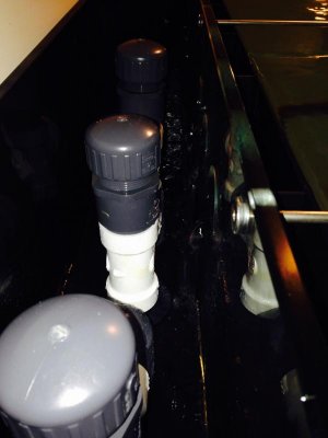
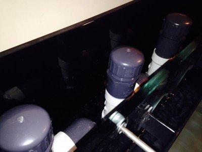
hey guys. I just turned on my new tank and I'm having trouble w the bean animal gurgling water. Im not sure if i need to raise the height of the other two pipes but the water drains faster than i can create the syphon.

Any thoughts?
 

Attachments

  • FullSizeRender-1.jpg
    FullSizeRender-1.jpg
    34.3 KB · Views: 2
  • FullSizeRender-3.jpg
    FullSizeRender-3.jpg
    34.4 KB · Views: 2
Back
Top