Silent and Failsafe Overflow System

Would it be smart to first buy my overflow box then base my holes of of the box placement & size?

It would be smart NOT to buy an overflow box, rather build your own that reflects the efficiency that is sorely lacking in manufactured OBs. Very long flat weirs, and intended specifically for systems as they are run today, not yesteryear. It is also wise to NOT fab the box till after the holes are punched, and bulkheads and elbows installed. This is so you don't end up with a box that is too short, or way taller than it needs to be.

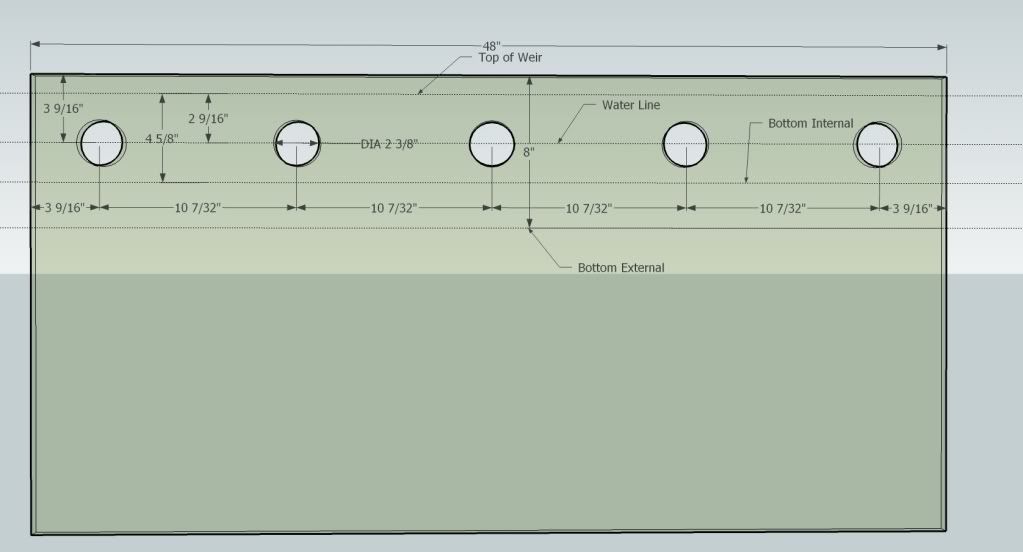
Hole placement is as mmn described. It is important to keep clear whether the dimension you are using is to the hole edge or the hole center. I try to be consistant, but I have used both myself. Also, depending on the type of system you are building, some sets of measurements are going to be completely wrong.

Holes need to be 1 hole diameter down from the top edge of the glass, or the bottom of the trim lip on the inside of a rimmed tank (I have a drawing posted that illustrates this.) To hole center, that would be 1.5 hole diameters. The hole needs to be lower however for the bulkhead flange to clear the tank trim. mmn's 1/4" is fine (depending on the bulkhead.)

From hole to hole, there needs to be 1 hole diamter edge to edge, or 2 hole diameters, center to center.

For internal/external (which is more trouble than it is worth) it is all different. Following the above placement guidelines will likely get you into some trouble.
 
Last edited:
This is posted in this thread a couple of times already, but I can't find it. It shows an "idealized" pass through for an internal/external on a 48" tank, with full length setup.


I don't think that your flow rate ~ 750 - 800 gph max, justifies the use of 1.5" bulkheads, 1" bulkheads, as in the original design will be more than adequate. Schedule 80 bulkheads are never justified, as black ABS bulkheads are fine; they are optional however, but have a smaller inside diameter.
 
NM, the quote has the correct information. It is close, but not quite right for 1.5" bulkheads. I should probably duplicate it and make some adjustments.
 
Yeh I plan on building my own with no teeth. So let me see if I am getting this all right. The top of my weir will be about level with the bottom of the trim because that is most likely my desired water line. 1 inch below that will be the tops of my downturns elbows. So to calculate exact center hole position of my 1 inch piping will be 1.5 inches below top of weir? Make sense?
Is there a generally good width for the ob if using 1" fitting?
Also, I believe uncle said earlier that ob depth doesn't matter?
What should I make the ob out of? Glass? Acrylic?

I don't mean to be annoying I'm just New to this & it can be difficult to wrap my head around. I have read as much as I can and apologize if I make people have to repeat themselves.
 
Last edited:
Yeh I plan on building my own with no teeth. So let me see if I am getting this all right. The top of my weir will be about level with the bottom of the trim because that is most likely my desired water line. 1 inch below that will be the tops of my downturns elbows.

In a nutshell, yes.

So to calculate exact center hole position of my 1 inch piping will be 1.5 inches below top of weir? Make sense?
Not really, no. That assumes that the outside diameter of a 1" elbow is 1", which it is not, and the inside diameter of a 1" elbow is not, and the outside diameter of 1" pipe is not. The inside diamter of the pipe is the only thing that is 1" in diameter. Depending on the sch or SDR (wall thickness) of the pipe, even that is not true. The only thing that is consistant is the outside diameter of the pipe, which is 1.315". Somewhere in this thread or another, I went through this piece by piece. I really don't want to do it again. :)

Is there a generally good width for the ob if using 1" fitting?
Also, I believe uncle said earlier that ob depth doesn't matter?
Wide enough to get your hand in, and get the elbows out, assuming threaded street ells. If using socket ells or street ells, then you need enough with to get both the elbow and bulkhead out. A good incentive to spend the time to find threaded street ells.

The depth does matter, and it does not matter, it depends on the context. Elbow clearence it matters. You need ~ 3/4" below the elbow inlet. So when trying to stuff this in a 2" tall OB, yeah it matters, when an OB is 10" tall, the depth is irrelevant.

What should I make the ob out of? Glass? Acrylic?

A debatable question. Aside from the fact that sillycone does not bond to acrylic, acrylic bows unless you get crazy with the thickness, and even then it will still bow some, most noticeable on a C2C. Glass is more stable, and 9mm glass at a shallow depth is not going to bow much, which leaves just the length to contend with. The longer the weir is, the easier it is to bow glass, so it depends.

I tell folks to use glass on glass, and acrylic on acrylic. The OBs we talk about here are not corner overflows, (which are predominately ABS now days,) so they don't behave the same way as in long unsupported spans.
 
Ok then 1 inch plus half the diameter of my elbow would suffice? Does it really matter if I'm off a tiny bit or can I just plan on drilling the hole center like 1.75 inches from top of weir?

Also what size whole will I need to drill for a 1 inch bulkhead? I have seen all different answers.

I would like to just go by your advice on this thread(http://reefcentral.com/forums/showthread.php?t=2215682&highlight=bean+animal+holes) and have center of holes 3.25" from top of trim.
 
Last edited:
The elbows should be 1" below the low point between the teeth.

Based on my lastest calculation, the elbows in my OB are 1/2" below that low point in between the teeth. So, other than removing the teeth from the equation can the 1/2" work or should I take a half inch off the three pipes within the box? As it stands right now, with the water line in the OB just about at the mid mark of the elbow, the water falls 1/2" plus about 5/8" which is a 1 1/8" . If I lower the elbow another 1/2" and maintain the same height of water at the mid mark of the newly positioned elbow, the water will fall 1 5/8" which would cause more bubbling in the OB. Unless I am missing something, anyway.

Please advise and thanks for your patience!!!

Not an artist so try not to giggle too loudly:
picture.php
 
Last edited:
For a 1" bulkhead its a 1.75" hole (45mm).

I'm going to amend this a bit. It matters what BH you have. From the BRS website:

For ABS BH - 42mm
For Sch 80 - 48mm

If you are using something else, there are Sch 40 BH, there might be different sizes.

It's really best to have the BH in hand so you can measure. There is a bit of leeway because the flange is quite a bit larger than the shaft.
 
Based on my lastest calculation, the elbows in my OB are 1/2" below that low point in between the teeth. So, other than removing the teeth from the equation can the 1/2" work or should I take a half inch off the three pipes within the box? As it stands right now, with the water line in the OB just about at the mid mark of the elbow, the water falls 1/2" plus about 5/8" which is a 1 1/8" . If I lower the elbow another 1/2" and maintain the same height of water at the mid mark of the newly positioned elbow, the water will fall 1 5/8" which would cause more bubbling in the OB. Unless I am missing something, anyway.

Please advise and thanks for your patience!!!

Not an artist so try not to giggle too loudly:
picture.php


In my overflow the water level is about 1.25" below the top of the weir. Putting the top of the elbow ~1". When everything is tuned the water level is not quite covering the fittings. Bad pic... Lights are still off.

b057dc1f84217bb44a74f9f71d41a503.jpg
 
In my overflow the water level is about 1.25" below the top of the weir. Putting the top of the elbow ~1". When everything is tuned the water level is not quite covering the fittings.

So, based on your water level, mine is a bit low. I think to cover my elbows as you are, I would need to raise my water level about 3/4" as it is about at the mid line of the elbow horizontal branch now.
 
Elbow Styles in Overflow

Elbow Styles in Overflow

I have these two styles available. One has a sharp bend and the other has a flange and a softer bend. Is there a preference out there for one style over the other?

Regards
Michael
 

Attachments

  • elbow a.jpg
    elbow a.jpg
    2.1 KB · Views: 1
  • elbow b.jpg
    elbow b.jpg
    2.8 KB · Views: 5
I have these two styles available. One has a sharp bend and the other has a flange and a softer bend. Is there a preference out there for one style over the other?

Regards
Michael

The picture of the elbow that is sharp 90 is the type that most folks use and that can be see in the BeanAnimal figures. So that would certainly be the most used successfully.
 
I have these two styles available. One has a sharp bend and the other has a flange and a softer bend. Is there a preference out there for one style over the other?

Regards
Michael

There is really no advantage to using sweeps for the intake ells. They take up a lot of room, and other that slightly less turbulence, similar to sanitary tees vs standard tees, they will not really improve the performance of the system. Stick with standard, or preferably street ells—Spigot x Socket or Mipt x Socket, depending on the bulkheads you have.
 
Hi,

I am on plumbing stage my reef tank project. This is based on a 120G tank with a 42G sump lockated in the basement. I have 3m (118") height difference. First i planed to use 1.57" (40mm) (1.41" internal) pipe for all three drain type. Since i purchase my return pump (ATK MP6055) that wil provide at max. a 715G return flow. I had enough pipe stock but to maximise return flow i choose to swap from 1.25" to 1.57" for return pipe. So the meaniong is to use for full siphon stand pipe the living 1.25" pipe. Beananimal online calculator give me ~3800G/h (see attachement). This is a huge amount 5.3x time the return i have....Am i wrong or can i use safely this 1.25" (1.023" internal) for full siphon drain.... I will not use bulkhead but Unseal join so internal pipe will not be reduced. Thefull siphon ball valve will be lockated in the basement just befor the drain enter in the sump. Full siphon drain pipe will be submerged in sump but not sure for open air drain pipe.

Regards Marc
 

Attachments

  • Capture d'écran 2014-12-16 11.41.32.png
    Capture d'écran 2014-12-16 11.41.32.png
    56.1 KB · Views: 1
Last edited:
Hi,

I am on plumbing stage my reef tank project. This is based on a 120G tank with a 42G sump lockated in the basement. I have 3m (118") height difference. First i planed to use 1.57" (40mm) (1.41" internal) pipe for all three drain type. Since i purchase my return pump (ATK MP6055) that wil provide at max. a 715G return flow. I had enough pipe stock but to maximise return flow i choose to swap from 1.25" to 1.57" for return pipe. So the meaniong is to use for full siphon stand pipe the living 1.25" pipe. Beananimal online calculator give me ~3800G/h (see attachement). This is a huge amount 5.3x time the return i have....Am i wrong or can i use safely this 1.25" (1.023" internal) for full siphon drain.... I will not use bulkhead but Unseal join so internal pipe will not be reduced. Thefull siphon ball valve will be lockated in the basement just befor the drain enter in the sump. Full siphon drain pipe will be submerged in sump but not sure for open air drain pipe.

Regards Marc

Has some one an opinion about what i describe over?

Marc
 
SO I am setting up a 40b tank and has some holes in the back. I'd like to do a C2C inside the tank and being there are 4 holes in there what can I do to create the Bean? In the crude pic I attached you can see the dimensions of where the holes are. The outer 2 are for 1" bulk(1 3/4) and the inner 2 are for 3/4"(1 1/2). At one time I had overflow boxes in the corners and return lines in the middle. I can always put the return line over the top edge. The holes are down 2" center from the plastic frame edge on the outside of tank.
Thanks,
Steve

picture.php
 
I am curious to know if anyone has any photos of a ghost overflow that is coast to coast with the bean animal method and return with the coast to coast.

If so, could someone PM me some photos or simply post here. Thanks much!
 
I am curious to know if anyone has any photos of a ghost overflow that is coast to coast with the bean animal method and return with the coast to coast.

If so, could someone PM me some photos or simply post here. Thanks much!

^ I am also interested in photos of this.

We are in the process of having a 400G built by AGE (96x36x27H). Been planning external overflow using BA drains. Tank will be against a wall so the holes need to be on the bottom of the overflow. Talked to AGE and they said the can do an 84" coast to coast style external with the overflow CNC'd into the back panel. I may just go over the top with the returns for simplicity.

Any experts have any opinions/advice on how I should set it up? How would you set it up if it were yours?

You only get one chance to build the tank so I want to do it right. Thanks!

Your question earlier was a bit to wide scoped to answer without typing for most of the day. ;)

Here is a large tank, using "cutouts" in the back panel for the overflow, and an external box with a BA setup. If you can limit the scope of your questions, it will be easier to give an answer. :)

http://www.reefcentral.com/forums/showthread.php?threadid=1482007&perpage=25&pagenumber=1
 
Back
Top