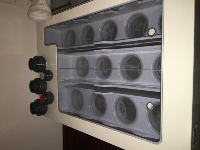
Silent and Failsafe Overflow System
It's gets really old seeing someone being torn down for wanting to splurge on certain things that the majority of reefers don't. The way that filter sock system works is that water flows over each row sequentially. When you have a sock plug up and start to overflow it's obviously not filtering anymore, so the next row is there to catch what is being missed from the second and so on. I can clearly see this when I clean my socks. The first row is filthy while my second row is much less dirty. I would bet money that you use some form of mechanical filtration on your sump and if you don't you would be cleaning detritus out of it a few times a week. Filter sock vs filter floss/sponge filter to me is an argument of preference not superiority. It takes me 5 min twice a week to walk outside and spray off my filter socks. It's much easier and faster than any thick piece of foam I have ever used. I rotate out sets of filter socks each time so I don't have to clean them right that second to keep my filtration going.
Also we are all aware that you can make a DIY sump yourself but not everyone can make one that's pleasing to the eye. Some of us almost like the gadgets and equipment we have as much as the livestock. My stand is open and my sump area is on display. I wouldn't want some 40g Breeder down there with **** poor seams for everyone to see when they come over. You don't know anything about this guy, his interests, or even his setup.
If you want high end, hassle free equipment and also a sump that was built and designed extremely well to house it and maximize functionality then RE is not that bad at all. Try to get any other sump maker to quote apples to apples what RE is providing it won't be much off. I've had a more economical sump from Lifereef which everyone raves about but it was tiny, I had no access to reach or clean anything without removing all my equipment from the sump. The filter pad did almost nothing. There was only 1 drain line hookup and you are SOL for bean animal style. No covers, lots of noise and salt creep and believe me that setup wasn't cheap.
So yeah I'll gladly pay what I paid for my RE system to have a sump that is virtually silent with the filter sock silencers, plenty of room for additional equipment and cleaning, cable holders all around the sump for nice orderly runs of your wiring, clear pvc lids that aren't cheap acrylic that will never yellow or bow with time, arguably the best skimmer in the industry, etc.
Also if this guy had the money to spend what he spent on that sump then I'm pretty sure livestock and equipment aren't going to be an issue for him.
Sent from my iPhone using Tapatalk

")