Silent and Failsafe Overflow System

Ok, I finally finished Beananimal coast to coast internal overflow system and yesterday started filling RO/DI water. Water passed through overflow and through siphon&openchannel standpipes, started to fill the sump. After water level passed the pump, wanted to give it a try to see how the system behaves. Return pump is Jebao dc-10000 so I decided to use it at lowest setting.

Short: Disaster.

Long:
First I must thell this is my first hands-on experience with a sump system below the tank, therefore be prepared to hear some stupid mistakes and second, the disaster is mainly not related to beananimal system.

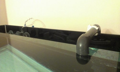
Return pipe (all of the pipes are 1.25", btw) do not come to DT through holes but draws an U shape over the tank.
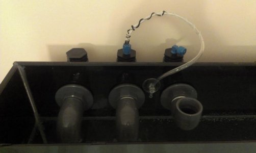
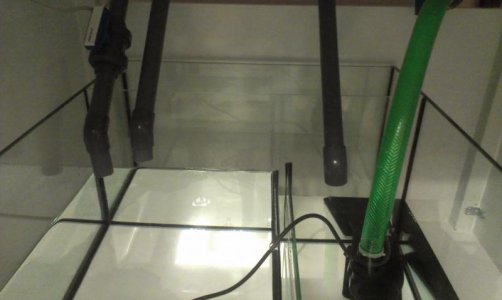
When I turn on the pump, everything was more or less ok, overflow filled and after a certain level, it started to drain. But, via openchannel and emergency pipes! The siphon was simply doing nothing. May worth to mention, siphon and openchannel pipes' sump ends were deeply submerged in water already even before running the pump. When I check with my hand, in the sump, openchannel was strongly pushing a good amount of water to sump (almost full capacity of pipe) and siphon was doing nothing other then releasing some air bubbles into overflow in every few seconds. So, obviously it was not functioning and heavy load was on shoulders of openchannel.

I was trying to understand why it happened this way and realised I completely forgot to put a tubing to the fitting which is waiting openly on top of openchannel. I asked my buddy to close the fitting by fingertip to see how the water level will react. While I was sitting in front of sump, he alerted me that water is rising and rising and my reaction was to turn off the pump. What a mistake! Return pipe's DT end was submerged also and as soon as I turn off the pump, reverse-siphon to the sump was started but It took a few valuable seconds for me to get whats going on. I blocked return pipe's tank end with my palm and at the same was trying to take it out of waterlevel (Thanks to Uncle and others who recommended return pipe runs over the tank, instead of drilling for the return hole, this way, it was not fixed and I was able to take it out of water after struggling for a short while, to break back-siphoning).

After collecting a bucket of water from ground, we moved return pipe out of water level, temporarily fixed there and decided to give it another try, this time, open channel air hole blocked from beginning and siphon and OC pipes' sump ends were kept out of water. Both siphon and OC pipes worked this time and water never reached to entrance of up-turned emergency elbow, but after a certain level in OFlow, it quickly drained with a lot of noise, then overflow refilled, then emptied again, a cycle with no end.

I can see its possibly related to the tubing over OC, but do not know at which level its end should be positioned at. Also, wondering how to prevent back-siphon, in case of electricity-failure or similar case, since I want to submerge the return pipe to tank to stop noise. I just put some soft tubing to OC (see pics below) but will change it tomorrow to something more robust. Meanwhile, I want to hear your opinions on my mistakes.

Regards,
 

Attachments

  • IMAG1583.jpg
    IMAG1583.jpg
    25.5 KB · Views: 5
  • IMAG1584.jpg
    IMAG1584.jpg
    33.8 KB · Views: 5
  • IMAG1585.jpg
    IMAG1585.jpg
    28.4 KB · Views: 4
Fairly simple to figure out.

Initial problem: siphon and open channel outlets too deep in the sump. This causes the open channel to take most of the flow, and the head height cannot rise high enough to purge the air out of the pipe. All outlets from the drain lines should be <= 1" deep in the sump.

Current problem: The airline inlet is way too deep in the overflow. This causes the open channel to trip to siphon before the siphon is fully started. Therefore the siphon does not purge the air out, and of course because the open channel is taking too much flow, the water level will not reach the dry emergency inlet. The air vent inlet should be placed higher than the inlet to the dry emergency.

It is not clear, whether you corrected the first problem, however both issues need to be fixed, before trying to fire it up again.

You also need to make sure of the next issue as well:

As far as the back siphon, there is nothing that you can do to prevent it, that will be 100% reliable. The flood proofing of the system is managed in two ways that are foolproof:

1) Enough spare empty volume in the sump to contain all power out drain down.

If the sump is not capable of containing all the power out drain down, then you need to redsign the sump so that it does, or replace the sump, with a sump that does. The failure probability of check valves is 100%, and the failure probability of anit-siphon holes is 99-100%.

2) Only submerge the return line outlet <=1" below the water level in the DT. This minimizes the amount of power out drain down from the tank.
 
Short: Disaster.

Close down the valve on the siphon so the level in the OF stays constant and does not drain, slurp!, and then drain again. The OC small hose should be above this level. You want it to convert to full siphon if the full siphon gets blocked.

If your sump is large enough, it will handle the drain down when pump is off. The return should be slightly below the normal running level of the tank to prevent noise and too much drain down.

It's important not to have too much water in the sump. If it's mostly full it won't have space for the drain down.

How about a pic of the sump when the pump is running and the siphon drain is balanced?

-----

Edit: Slowly typing while Uncle gives a great answer! :thumbsup:
 
I am setting up a 150g tall and I am setting up a beananimal drain system. My question is what size of bulk heads and drains to use. Based off all of my reading i think that 1.5" bulk heads and drain lines should be more then enough and i just was wondering what everyone thought. I do have 2" bulk heads right now that i could use. Do not want to have a "I should have done that" moment. Thanks
 
Close down the valve on the siphon so the level in the OF stays constant and does not drain, slurp!, and then drain again. The OC small hose should be above this level. You want it to convert to full siphon if the full siphon gets blocked.

If your sump is large enough, it will handle the drain down when pump is off. The return should be slightly below the normal running level of the tank to prevent noise and too much drain down.

It's important not to have too much water in the sump. If it's mostly full it won't have space for the drain down.

How about a pic of the sump when the pump is running and the siphon drain is balanced?

-----

Edit: Slowly typing while Uncle gives a great answer! :)

Ok, then I won't be too hard on you over this... ;)

The air vent line, comes last in the trip order. You do not want the open channel to trip to siphon, unless both the siphon and dry emergency block up. With the air inlet too low, as you describe, there are specific symptomatic start up issues, that involve the siphon not starting, (not purging the air,) and the open channel taking too much flow.

Reiterating, the air inlet should be higher than the inlet to the dry emergency.
 
I am setting up a 150g tall and I am setting up a beananimal drain system. My question is what size of bulk heads and drains to use. Based off all of my reading i think that 1.5" bulk heads and drain lines should be more then enough and i just was wondering what everyone thought. I do have 2" bulk heads right now that i could use. Do not want to have a "I should have done that" moment. Thanks

Unless you are planning on going over 1500gph, there is no reason in the world to use 1.5" bulkheads. 1.5" pipe yes, but the bulkheads only need be 1". With this latter setup, you should have no problem getting to 1500gph. If you have less than a 24" drop to the sump, this may need some reconsideration...

If your tank is truly a 150 tall, then you are going to want to hit 1500gph...tall dimensioned tanks are not 'good' marine system tanks. They are more geared towards freshwater systems.
 
Fairly simple to figure out.

Initial problem: siphon and open channel outlets too deep in the sump. This causes the open channel to take most of the flow, and the head height cannot rise high enough to purge the air out of the pipe. All outlets from the drain lines should be <= 1" deep in the sump.

Never imagined this might cause a problem but both outlets were extended-submerged "to the bottom" of sump, with help(!) of a couple of hoses. I removed these two extension hoses before taking pictures.
Current problem: The airline inlet is way too deep in the overflow. This causes the open channel to trip to siphon before the siphon is fully started. Therefore the siphon does not purge the air out, and of course because the open channel is taking too much flow, the water level will not reach the dry emergency inlet. The air vent inlet should be placed higher than the inlet to the dry emergency.

Ok, my mistake again, during flood, there were no airline installed at all. airline fitting (blue thing) was sitting there, open.

I just fixed the airline temporarily to show you the current situation and how things look like, and will arrange it according to the advises. But your last sentence confused me. If I place airline inlet "above" emergency, its practically turns to situation in my flooding experiment (There were no tubing at that time, fitting open, alone). Then what if again OC and emergency starts to drain instead of siphon pipe (The only difference will be outlets will be 1" submerged, instead of all the way.

It is not clear, whether you corrected the first problem, however both issues need to be fixed, before trying to fire it up again.

As seen in the pic, I removed the extension hoses from outlets, but before putting shorter versions back, I want to know if there is any adventage to keep OC hose a bit shorter then siphon hose. Or keep both equally submerged in water about 1" ?

You also need to make sure of the next issue as well:

As far as the back siphon, there is nothing that you can do to prevent it, that will be 100% reliable. The flood proofing of the system is managed in two ways that are foolproof:

1) Enough spare empty volume in the sump to contain all power out drain down.

If the sump is not capable of containing all the power out drain down, then you need to redsign the sump so that it does, or replace the sump, with a sump that does. The failure probability of check valves is 100%, and the failure probability of anit-siphon holes is 99-100%.

This is where things get complicated. I am afraid I reserved largest XY area to PS zone, and unfortunately, Z area also, by keeping the seperator too high then actually needed (Only now I can see it). This leaved a smaller volume to pump. I will make some math to see how much water that area can handle before flooding and how many milimeters of submersion it equals at return outlet, above. If it comes out it is barely enough, I wont take risk and redesign the sump.

2) Only submerge the return line outlet <=1" below the water level in the DT. This minimizes the amount of power out drain down from the tank.

I will do this as described above.

And thank you very much for detailed responses, I appreciate.
 
Close down the valve on the siphon so the level in the OF stays constant and does not drain, slurp!, and then drain again. The OC small hose should be above this level. You want it to convert to full siphon if the full siphon gets blocked.

Then the cycle is broken only by adjusting the siphon valve. Thanks !

If your sump is large enough, it will handle the drain down when pump is off. The return should be slightly below the normal running level of the tank to prevent noise and too much drain down.

It's important not to have too much water in the sump. If it's mostly full it won't have space for the drain down.

My sump is not so big, but we will see, after some math, see my above post.

How about a pic of the sump when the pump is running and the siphon drain is balanced?

After succesfull run, I will. :)

-----

Edit: Slowly typing while Uncle gives a great answer! :thumbsup:


Thanks for all the answers !!!!!!
 
Never imagined this might cause a problem but both outlets were extended-submerged "to the bottom" of sump, with help(!) of a couple of hoses. I removed these two extension hoses before taking pictures.


Ok, my mistake again, during flood, there were no airline installed at all. airline fitting (blue thing) was sitting there, open.

I just fixed the airline temporarily to show you the current situation and how things look like, and will arrange it according to the advises. But your last sentence confused me. If I place airline inlet "above" emergency, its practically turns to situation in my flooding experiment (There were no tubing at that time, fitting open, alone). Then what if again OC and emergency starts to drain instead of siphon pipe (The only difference will be outlets will be 1" submerged, instead of all the way.

The idea is to allow water to flow in the dry emergency without tripping the OC to siphon. This is a matter of having the air inlet high enough that water will flow in the dry emergency without submerging the air inlet line. This is according to the design criteria, and it works fine this way. The odds of flooding are slim to none. As soon as the air vent is submerged the OC trips to siphon, and the water level drops rather quickly, however, the only way it should trip, or need to trip, is as a last resort, with both the siphon and dry emergency fully blocked.


As seen in the pic, I removed the extension hoses from outlets, but before putting shorter versions back, I want to know if there is any adventage to keep OC hose a bit shorter then siphon hose. Or keep both equally submerged in water about 1" ?

No, there isn't. All pipes should be equal length (as close as possible) and terminate at the exact same level @ <=1" below the sump water level.


This is where things get complicated. I am afraid I reserved largest XY area to PS zone, and unfortunately, Z area also, by keeping the seperator too high then actually needed (Only now I can see it). This leaved a smaller volume to pump. I will make some math to see how much water that area can handle before flooding and how many milimeters of submersion it equals at return outlet, above. If it comes out it is barely enough, I wont take risk and redesign the sump.


I will do this as described above.

And thank you very much for detailed responses, I appreciate.

Welcome...
 
Well, things are more or less sorted, siphon and OC outlets submerged to sump a bit less then an inch, and now system works without any cycle issue, each and everytime I stop and restart the return pump. I arranged submerging distance of return pipe to DT, so the sump now can handle the back-siphon water, there is a little overhead, like 6-7 liters, but seems ok. Currently the only apparent issue is bubbles coming from siphon, I discovered one screw connection (leaks from threads I guess) causes this and tried to cover it with several folds of teflon tape, bubble amount and size are quite minimized after that, but they still exist, this time without any audible noise.

In this point I should ask whether is it critical to completely prevent tiny amount of air leak at the siphon line or can we live with some small bubbles, considering the PS will stay in that department, also. I could not find a way to reveal remaining air leak points...


Air leaks in a siphon line are a tough problem to track down. Often, there will be no water leak associated with the air leak, as water tight is not quite the same as air tight.

Tape does a poor job of sealing pvc threaded fittings. What is supposed to be used for pvc threaded fittings is a non-hardening thread sealant, which is a semi-liquid substance.

Although threaded fittings are the most likely area for air leaks, poorly glued socket joins can leak air as well. There is no simple solution, other than to rebuild the drain line. I think you should make every effort to eliminate the air leaks, as they can and do affect the operation of a siphon. We are not building spacecraft or sending things into space, but to be just a little philosophical, we only achieve things by striving for excellence, rather than mediocrity. But then there is another philosophy that says if it ain't broken, don't fix it...
 
Since its running with RO water at the moment, I can do what ever I want, and yes I am one of those seek for excellence (part of hobby). After emptying the overflow, I will remove the siphon line, plug inflating outlet of our house vacuum to siphon pipeline and will lock the other end. Then apply some detergent to joints to see whats going on. At least, this is the plan. If all fails, I will rebuild.

And for threads, I am not sure that I am willing to apply some kind of semi-liquid chemicals to threads. I used pvc welding glue for glue points, applied to both sides, a good amount. Though not sure what to do if it comes out threadleak.

A non-hardening thread sealant is what is called for to accomplish sealing the threads. It is more of a paste than a semi-liquid, poor choice of words on my part, but wanted to make a distinction between thread sealant and pipe dope/Teflon paste. Teflon tape is unsatisfactory, because it deforms the threads as well as the fitting itself. Both Lasco, and Spears sell the proper non-hardening thread sealant.

Although this fact sheet states that 'only a small percentage' of threaded fittings leak, (I find it far more common than a 'small percentage') the number of reasons are rather finite.

http://www.lascofittings.com/threads
 
Nice info on Lasco page. I will check if somebody is selling anything similar in Turkey. One thing is when I first started the system yesterday, which worked about 3-4 hrs, there were no air bubbles from siphon, it started today, may mean pre-loaded teflon tape on hidden threads is slowly failing.

Here are some images from build of bulkheads;
https://www.dropbox.com/s/9qp2aayt2drrt5e/IMAG0422.jpg
https://www.dropbox.com/s/d2y5m9xnps0lhg3/IMAG0707.jpg
https://www.dropbox.com/s/4yc6842dsy0p4j0/IMAG0708.jpg
https://www.dropbox.com/s/20km7s2fbfihwux/IMAG0706.jpg
https://www.dropbox.com/s/2jj2yqyinucmone/IMAG0732.jpg
https://www.dropbox.com/s/z2re7904ugw0cv4/IMAG0730.jpg

First image is an overview of bulkhead I am using (except, there is one rubber washer installed, to water side). Last image was taken before applying the teflon tape to the threaded pipes extending from rear side of aquarium, during initial tests. It currently has plenty on threads, as seen in previous pic. In short, I put teflon tape to every piece of thread covered by another pvc piece.

I have a friend I have known since the early 1970's that lives in Istanbul, however, we don't exactly discuss where to purchase plumbing supplies... ;)

I cannot say where to walk in and purchase it, but I do know it is available in Turkey.

http://rectorsealturkiye.com/en/index.asp?id=4

Looks to me like you are using a whole lot of tape on those threads, which is not a good thing, and you have way too many threaded fittings. That may be a matter of availability, however.
 
Thanks, again you surprised me, I did some google search on this brand but unfortunately nothing come out, after reading some from your link I realised that this type of sealant is widely available in TR, but under a quite different name, something like "liquid washer" ("sıvı conta", for tr readers). I have some more ideas on investigation of air leak, need to buy something first and will inform further if it goes as planned.
 
So Ive figured out that with my tall overflow I need my drain pipes deeper in the sump so it creates more head pressure in the overflow so that I dont get the "waterfall" effect in the overflow. Gonna start at an inch from the bottom of the tank and go from there. Will post the results once I try it.
 
Extending the siphon standpipe deeper into the sump will only create startup problems by preventing the pipe from easily purging the air. The "head" pressure is the same and is measured from the surface of the intake pool (the water level in the overflow box) to the surface of the discharge pool (the water level in the sump).

Your sump could be 100 feet deep and the operating head would not change (lets ignore the friction from the long pipe), regardless of how deep the pipe went.
 
The head pressure changes depending on how deep your overflow is and how far down the your down turned pipes are. My system is proof of it. I drilled my holes to far down by a few inches . By making the stand pipes shorter today it made the lvl in the overflow lower,which in turn made the siphons start sucking air. Therefore by extending the stand pipes deeper it will raise the water lvl in the overflow.

At least in theory anyway. If it doesnt work I'll try to come up with something else but as is its not working properly and I have to fix it.
 
No, the head pressure depends on where the water level is in the overflow in relation to the water level in the sump, not how deep the overflow is, or where the elbows are...however raising the water level in the overflow increases the head pressure on the system as a whole. However, the depth of the pipes in the sump, will have a negative affect on the starting characteristics of the system. The volume of informaton on this topic is very clear.

The way your system is implemented, there is not a whole lot you can do about the height of the water fall, at this stage in the game. What needs to be done, is to raise the point where the water starts heading down, which is usually external to the tank.


OOPS you made an error in the hole placement, the world is not going to come to a screeching halt. Your water fall is a bit high, and you have some noise. I don't remember that far back, but if your overflow is not C2C, lengthen it to C2C that will quiet down the overflow a bit, maybe a great deal.
 
Last edited:
Back
Top